In addition to its roles in controlling motors, LCDs, and LEDs, the Arduino also possesses the capability to gauge temperature measurement. By connecting an analog temperature sensor to the Arduino, it can function as an electronic thermometer. This section will guide you through the process of establishing connections and testing the precision centigrade temperature sensor. Additionally, you will gain insights into constructing an electronic thermometer utilizing the sensor and readily available electronic components. Moreover, you will acquire the know-how to exhibit the collected data through a serial monitor and an LCD. Lastly, you will be instructed on how to wire a DC motor to facilitate temperature regulation for electro mechanics. Figure 1 depicts the necessary components essential for conducting these hands-on projects and experimental endeavors.
Parts List
1 Arduino Duemilanove or equivalent
1 LM35 precision centigrade temperature sensor
1 10K potentiometer
1 2N3904 NPN transistor
1 small DC motor
1 1N4001 diode
1 1K resistor
1 100W resistor
1 16×2 LCD
1 SPST switch
1 LED
Solderless breadboard
22 AWG solid wire Digital multimeter
Oscilloscope (optional)
Electronic tools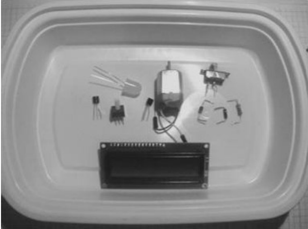
What Constitutes a Centigrade Temperature Sensor with High Precision?
A precision centigrade temperature sensor is an integrated circuit (IC) that generates an output voltage proportional to the Celsius temperature scale. It doesn’t necessitate external components for temperature accuracy calibration, as these are incorporated during the IC’s manufacturing process. If you wish to integrate external readout devices such as LEDs or LCDs with the sensor, it’s easily achievable due to the IC’s low output impedance, a proportional output driver circuit, and accurately integrated calibration components. These attributes facilitate the proper operation of these optoelectronic displays.
An additional impressive aspect of the precision centigrade temperature sensor is its capability to function with either a solitary DC power supply or a bipolar (positive/negative) voltage source, making it especially convenient for enthusiasts and hobbyists. Utilizing a temperature measurement IC is straightforward – you only need to connect three wires to the device and supply it with a DC power source.
How It Works
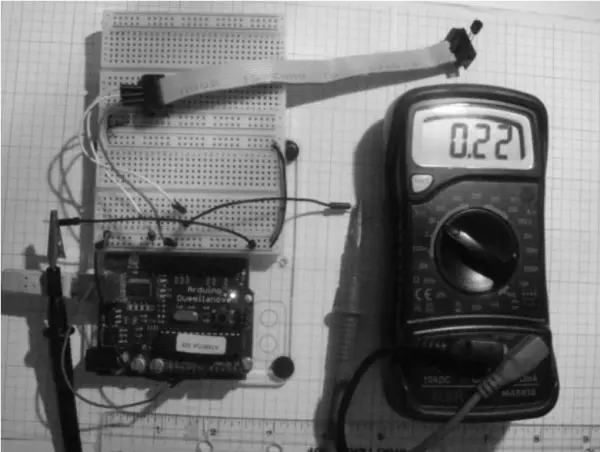
The output voltage of the temperature sensor IC corresponds to the temperature on the Celsius scale. In room air, the LM35 temperature sensor produces an output of around 0.23 V. When the IC is subjected to heat, its output voltage experiences an increase. To observe the fluctuating output voltage of the sensor, you can connect a voltmeter to the IC’s output pin. Figure 2 illustrates the system block diagram for monitoring the output voltage of the temperature sensor.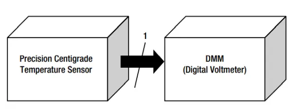
Utilizing the system block diagram as a blueprint, it is possible to construct a basic electronic thermometer. Employing the block diagram depicted in Figure 2, I designed the schematic diagram for the uncomplicated electronic thermometer circuit, as illustrated in Figure 3.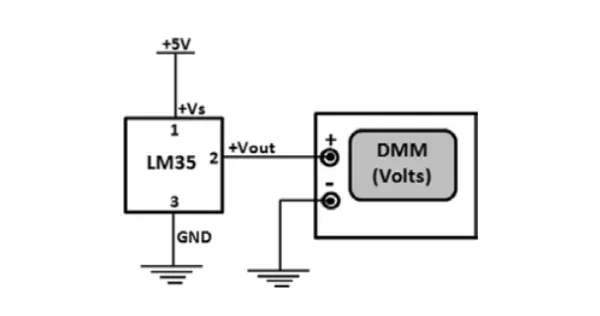
Building an Electronic Thermometer
During the construction of the electronic thermometer, I opted for a repurposed computer ribbon cable instead of soldering the sensor onto a prototype board. This choice facilitated unrestricted movement of the sensor. The ribbon cable’s utility lies in its ability to enhance the sensor’s connection to the Arduino; by inserting the IC’s three pins into the openings of the connector, flexibility is achieved. On the opposite end of the ribbon cable connector, extension is achievable by introducing wires. By using longer wires, I can adjust the ribbon cable’s length accordingly. Alternatively, if you possess an alternative method for enabling the sensor’s free movement for remote temperature measurements, it’s worth exploring. For reference, Figure 4 presents an illustration of the temperature sensor affixed to the computer ribbon cable.
I employed an ohmmeter to align the temperature sensor pins, inserted into one connector, with the wires affixed to the opposing end of the computer ribbon cable. During this assembly stage, I set the ohmmeter to continuity mode to ensure accurate matching of the sensor pins with the jumper wires. For further clarity, Figure 5 provides a detailed view of the connectors at the end of the ribbon cable.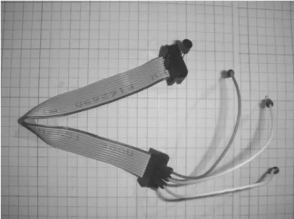
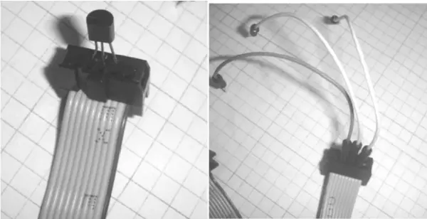
I followed the pinout specifications from the LM35 datasheet to connect the sensor IC to the ribbon cable’s end connector. The pinout layout of the LM35 is illustrated in Figure 6. With the ribbon cable assembly in place, I proceeded to perform the ultimate wiring of the uncomplicated electronic thermometer on the solderless breadboard. The finished electronic thermometer is depicted in Figure 7.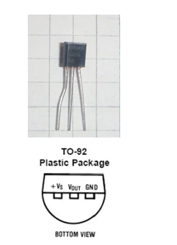
A Computer Thermometer
Crafting a computer-based thermometer entails substituting the DMM digital voltmeter with the Arduino-Processing Serial Monitor. Through the establishment of a serial connection with the computer, voltage readings from the temperature sensor become accessible. The system block diagram outlining the components of a computer thermometer is visualized in Figure 8.
For the conversion of temperature sensor data, the subsequent equation is employed:
Voltage at pin (Vpin) (readings from ADC) = ×(5000/1024)
The programming sketch for Arduino, responsible for converting temperature sensor data into voltage and presenting it on the Serial Monitor, is outlined in Listing 1.
Listing 1. LM35 Sensor Sketch
/* Converting LM35 Sensor data to Volts
Sketch will take sensor data and convert it to volts.
Volts value will be displayed on serial monitor
Remixed sketch of ladyada's TM36 sensor tutorial
http://www.ladyada.net/learn/sensors/tmp36.html
Don Wilcher 03/16/12
*/
//LM35 Pin Variables
int sensorPin = 0;// The analog pin the LM35's Vout is connected to.
/*
Initialize serial connection with the computer*/
void setup()
{
Serial.begin(9600); // Begin serial connection with the computer
pinMode(sensorPin, INPUT);
}

void loop()
{
int reading = analogRead(sensorPin);// read data from LM35 using Arduino (A0) pin
float voltage = reading *5.0;// Convert sensor data to voltage
voltage /= 1024.0;
Serial.print(voltage); Serial.println("volts");// Print voltage on serial monitor
delay(1000);// print data every second
}
The output voltage of the LM35 can be read using the Arduino’s analog pin (A0). The circuit’s schematic diagram is depicted in Figure 9.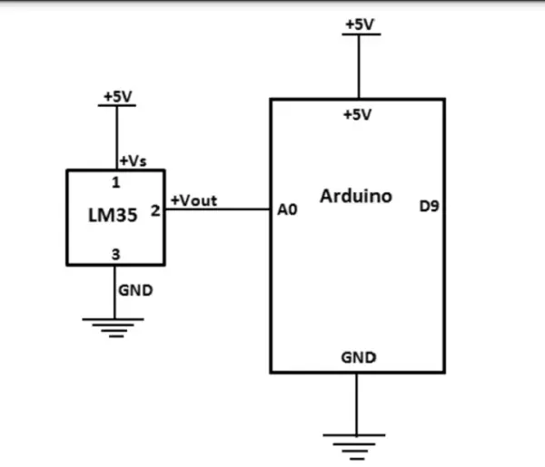
Once you’ve constructed the circuit schematic diagram, upload the sketch and initiate the Serial Monitor. Subsequently, you’ll observe voltage data scrolling across the screen, as demonstrated in Figure 10.
For handling the computer ribbon cable on the solderless breadboard, I positioned a jumper wire across it, as depicted in Figure 11.
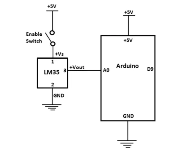
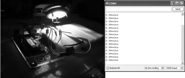
By integrating an SPST (single pole single throw) switch between pin 1 of the IC and +5VDC, you can interrupt the flow of data from the sensor to the Arduino. The circuit’s revised schematic diagram for the computer thermometer is presented in Figure 12. For prototype testing, I employed a bench light as a heat source. As I maneuvered the bench light towards the sensor, there was a discernible rise in the output voltage, as demonstrated in Figure 13.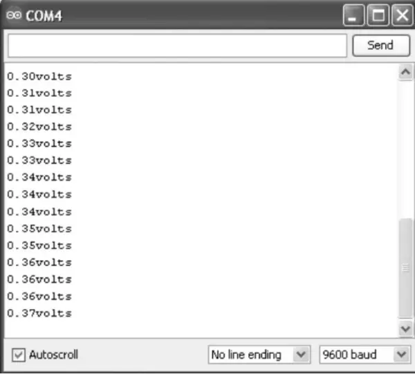

Final Completion of Computer Thermometer
Once the LM35 sensor circuit is operating accurately, you have the option to modify the sketch to display real temperature readings. Incorporate the subsequent lines of code into the LM35 sketch to enable the display of temperature data on the Serial Monitor:
Serial.print(voltage); Serial.println(“volts”); // Print voltage on serial monitor
float temperatureC=(0.5-voltage)*100; //Convert voltage to temperature
Serial.print(temperatureC); Serial.println(” degrees C”);// Print Temperature in C
Upload the modified sketch to the Arduino board to observe the voltage and temperature (in Celsius) values scrolling on the Serial Monitor interface. This presentation is exemplified in Figure 14.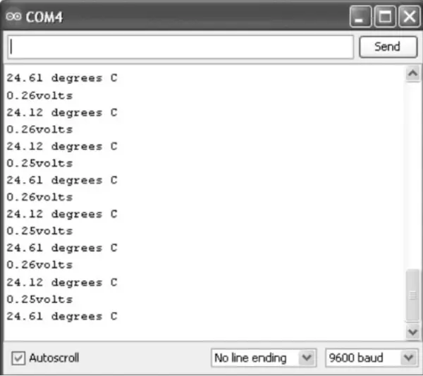
To show Fahrenheit temperature, you can use the following lines of code:
float temperatureF=(temperatureC*9.0/5.0)+32; //Convert voltage to temperature
Serial.print(temperatureF); Serial.println(“degrees F”);// Print Temperature in C
The outcomes of the modified sketch on the Serial Monitor are illustrated in Figure 10.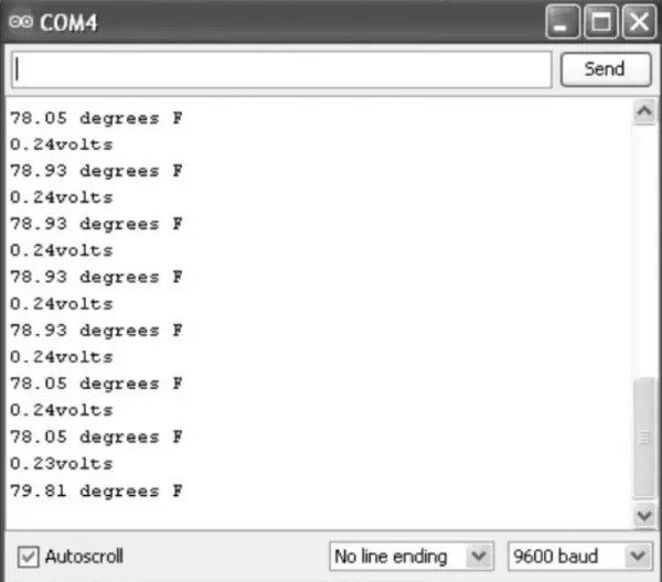
Listing 2 entails the sketch for exhibiting temperatures in Celsius, while Listing 3 demonstrates the presentation in Fahrenheit.
Listing 10-2 LM35 Celsius Temperature Sketch
/* Converting LM35 Sensor data to Volts
Sketch will take sensor data and convert it to volts.
Volts value will be displayed on serial monitor
Remixed sketch of ladyada's TM36 sensor tutorial
http://www.ladyada.net/learn/sensors/tmp36.html
Don Wilcher 03/16/12
*/
//LM35 Pin Variables
int sensorPin = 0;// The analog pin the LM35's Vout is connected to.
/*
Initialize serial connection with the computer*/
void setup()
{
Serial.begin(9600); // Begin serial connection with the computer
pinMode(sensorPin, INPUT);
}
void loop()
{
 int reading = analogRead(sensorPin); // read data from LM35 using Arduino (A0) pin
float voltage = reading *5.0; // Convert sensor data to voltage
voltage /= 1024.0;
Serial.print(voltage); Serial.println("volts"); // Print voltage on serial monitor
float temperatureC=(0.5-voltage)*100; //Convert voltage to temperature
Serial.print(temperatureC); Serial.println("degrees C");// Print Temperature in C
delay(1000);// print data every second
}
Listing 10-3. LM35 Fahrenheit Temperature Sketch
/* Converting LM35 Sensor data to Volts
Sketch will take sensor data and convert it to volts.
Volts value will be displayed on serial monitor
Remixed sketch of ladyada's TM36 sensor tutorial
http://www.ladyada.net/learn/sensors/tmp36.html
Don Wilcher 03/16/12
*/
//LM35 Pin Variables
int sensorPin = 0;// The analog pin the LM35's Vout is connected to.
/*
Initialize serial connection with the computer*/
void setup()
{
Serial.begin(9600); // Begin serial connection with the computer
pinMode(sensorPin, INPUT);
}
void loop()
{
int reading = analogRead(sensorPin); // read data from LM35 using Arduino (A0) pin
float voltage = reading *5.0; // Convert sensor data to voltage
voltage /= 1024.0;
Serial.print(voltage); Serial.println("volts"); // Print voltage on serial monitor float temperatureC=(0.5-voltage)*100;
float temperatureF=(temperatureC*9.0/5.0)+32; //Convert voltage to temperature
Serial.print(temperatureF); Serial.println(" degrees F");// Print Temperature in C
delay(1000);// print data every second
}
Try It Out!
The LM35 sensor proves to be an exceptional integrated circuit for temperature measurement purposes, as showcased in the computer thermometer project. By leveraging the fundamental sensor circuit along with the Fahrenheit sketch, you can combine them to create a temperature monitoring system. The system block diagram for a temperature monitor is depicted in Figure 16.
The underlying idea for the monitoring device revolves around deactivating the flashing LED when the temperature surpasses a predefined threshold value embedded within the sketch. The threshold value I incorporated is 78 °F, which exceeds the typical room temperature. The schematic diagram of the circuit, suitable for constructing the prototype temperature monitor, is presented in Figure 17.
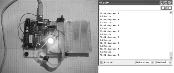
The prototype I assembled, following the provided circuit schematic diagram, is presented in Figure 18. Once the sketch provided in Listing 4 is uploaded to the Arduino, the LED will initiate a flashing pattern with a 2-second interval. By directing a breath of air onto the temperature sensor, the flashing LED will cease. While experimenting with various temperature extremes, observe the temperature readings as they cascade on the Serial Monitor. Modify the sketch to alter the flash rate and the threshold values, witnessing corresponding changes on the LED and the Serial Monitor display. Additionally, assess the sensor’s responsiveness between temperature fluctuations. Document your findings in a laboratory notebook.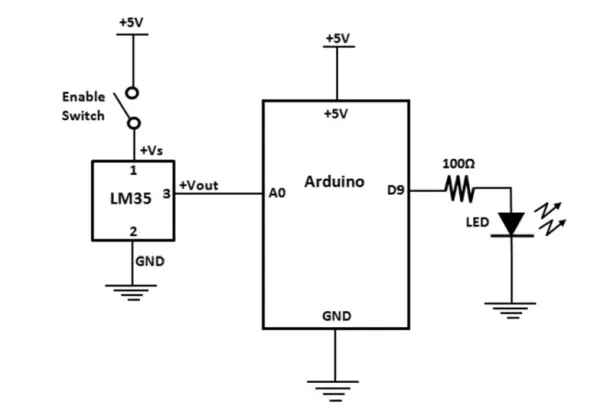
Listing 10-4. LM35 Farenheit Temperature with Flashing LED Sketch
/* Converting LM35 Sensor data to Volts
Sketch will take sensor data and convert it to volts.
Volts value will be displayed on serial monitor
Remixed sketch of ladyada's TM36 sensor tutorial
http://www.ladyada.net/learn/sensors/tmp36.html
Don Wilcher 03/16/12
*/
//LM35 Pin Variables
const int sensorPin = 0;// The analog pin the LM35's Vout is connected to.
const int ledPin = 9; //the number of the LED Pin
/*
Initialize serial connection with the computer*/
void setup()
{
Serial.begin(9600); // Begin serial connection with the computer
pinMode(ledPin, OUTPUT);
pinMode(sensorPin, INPUT);
}

void loop()
{
int reading = analogRead(sensorPin); // read data from LM35 using Arduino (A0) pin
float voltage = reading *5.0; // Convert sensor data to voltage
voltage /= 1024.0;
Serial.print(voltage); Serial.println("volts"); // Print voltage on serial monitor
float temperatureC=(0.5-voltage)*100;
float temperatureF=(temperatureC*9.0/5.0)+32; //Convert voltage to temperature
Serial.print(temperatureF); Serial.println(" degrees F");// Print Temperature in C
if(temperatureF >78){
digitalWrite(ledPin, HIGH);
delay(1000);
digitalWrite(ledPin, LOW);
delay(1000);
}
else{
digitalWrite(ledPin, LOW);
}
delay(1000);// print data every second
}
An engaging twist to the sketch involves varying flash rates based on normal and elevated temperatures. I replicated the flashing LED code and adjusted the duplicated version to flash more rapidly at higher temperatures measurement. Conversely, the LED maintains a slower flash rate at typical room temperatures. The remixed sketch, implementing this temperature monitoring effect, is depicted in Listing 5.
Listing 10-5. LM35 Farenheit Temperature with Dual LED Flash Rates Sketch
/* Converting LM35 Sensor data to Volts
Sketch will take sensor data and convert it to volts.
Volts value will be displayed on serial monitor
Remixed sketch of ladyada's TM36 sensor tutorial
http://www.ladyada.net/learn/sensors/tmp36.html
Don Wilcher 03/16/12
*/
//LM35 Pin Variables
const int sensorPin = 0;// The analog pin the LM35's Vout is connected to.
const int ledPin = 9; //the number of the LED Pin
/*
Initialize serial connection with the computer*/
void setup()
{
Serial.begin(9600); // Begin serial connection with the computer
pinMode(ledPin, OUTPUT);
pinMode(sensorPin, INPUT);
}
void loop()
{
int reading = analogRead(sensorPin); // read data from LM35 using Arduino (A0) pin
float voltage = reading *5.0; // Convert sensor data to voltage
voltage /= 1024.0;
Serial.print(voltage); Serial.println("volts"); // Print voltage on serial monitor
float temperatureC=(0.5-voltage)*100;
float temperatureF=(temperatureC*9.0/5.0)+32; //Convert voltage to temperature
Serial.print(temperatureF); Serial.println("degrees F");// Print Temperature in C
if(temperatureF >78){
digitalWrite(ledPin, HIGH);
delay(1000);
digitalWrite(ledPin, LOW);
delay(1000);
}
else{
digitalWrite(ledPin, HIGH);
delay(100);
digitalWrite(ledPin, LOW);
delay(100);
}
delay(1000);// print data every second
}
An LCD Electronic Thermometer
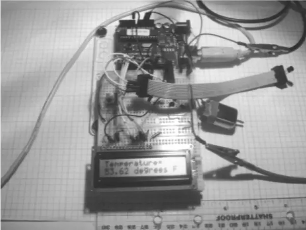
By utilizing the foundational circuit diagram illustrated in Figure 10-12 as the central measurement mechanism, it becomes possible to construct an intriguing electronic thermometer featuring an LCD display. The essential components required for this undertaking encompass the LCD screen and a pair of resistors. The configuration of the LCD electronic thermometer’s functional structure is depicted in Figure 19. During the circuit’s design phase, the inclusion of the LCD was instrumental in transforming the electronic device into a portable instrument suitable for temperature measurement readings in various field settings. If the intention is to exhibit temperature data on a computer interface, a USB connection can be established between the Arduino and a desktop PC or laptop.
In the process of linking the LCD to the Arduino, the power (Vdd) and ground (Vss) terminals are interconnected while the 10 K potentiometer is meticulously adjusted to eliminate pixel artifacts from the display. The LED backlight of the LCD is connected through a 100-ohm resistor. This preliminary phase is crucial to ensuring the proper functionality of the LCD prior to the final integration of its components with the Arduino. The complete schematic diagram of the LCD electronic thermometer circuit is visually outlined in Figure 12.
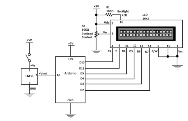
To simplify the wiring process with the Arduino, position the LCD in such a way that its pin 1 aligns with the corresponding row on the solderless breadboard. The ultimate prototype of the LCD electronic thermometer is displayed in Figure 21.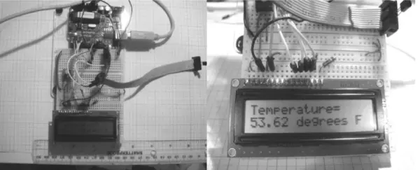
Once you’ve successfully loaded the sketch for the LCD electronic thermometer onto the Arduino, a temperature reading will promptly appear on the screen. Should you wish to elevate the temperature reading, a simple method involves positioning the sensor amidst your fingers. The temperature information refreshes at a 10-millisecond (ms) interval, a timing parameter that can be readily adjusted within the sketch using the delay(10) command. The comprehensive code for the LCD electronic thermometer is provided in Listing 6.
Listing 6. Sensor Data to Temperature Sketch
/* Converting LM35 Sensor data to Temperature
Sketch will take sensor data and convert it to volts then to temperature.
Volts and Temperature values will be displayed on serial monitor and LCD.
Remixed sketch of ladyada's TM36 sensor tutorial
http://www.ladyada.net/learn/sensors/tmp36.html
Don Wilcher 03/17/12
*/
//LM35 Pin Variables
int sensorPin = 0;// The analog pin the LM35's Vout is connected to.
#include <LiquidCrystal.h>
LiquidCrystal lcd(12, 11, 5, 4, 3, 2);
/*
Initialize serial connection with the computer*/
void setup()

{
Serial.begin(9600); // Begin serial connection with the computer
lcd.begin(16,2);
analogReference(INTERNAL);
pinMode(sensorPin, INPUT);
}
void loop()
{
int reading = analogRead(sensorPin); // read data from LM35 using Arduino (A0) pin
float voltage = reading *5.0; // Convert sensor data to voltage
voltage /=1024.0;
Serial.print(voltage); Serial.println("volts"); // Print voltage on serial monitor
float temperatureC=((100*1.1*voltage)/1024)*100;
float temperatureF=(temperatureC*(9.0/5.0))+32; //Convert voltage to temperature
Serial.print(temperatureF); Serial.println(" degrees F");// Print Temperature in C
// display Temperature on LCD
lcd.setCursor(0,0);
lcd.print("Temperature=");
lcd.setCursor(0,1);
lcd.print(temperatureF); lcd.println(" degrees F ");
delay(10);// print data every 10milliseconds
}
A Temperature Controller
Transforming the LCD electronic thermometer into a temperature controller necessitates the utilization of a handful of electronic components. A temperature controller functions as a mechanism to activate an external element, such as a light bulb or a motor, when the electrical signal from the sensor surpasses a designated threshold. In this context, the Arduino takes action by engaging a transistor-driven DC motor circuit when the temperature measurement surpasses the predefined value established within the sketch.
The sketch incorporates an established trigger value through if-else statements. By utilizing the “greater-than” sign, you establish a conditional arrangement within the sketch to monitor the temperature measurement of the sensor. When the temperature falls below the set threshold, the Arduino halts the motor; conversely, it activates the motor when the temperature surpasses the threshold. The schematic diagram of the temperature controller circuit is visually outlined in Figure 22.
The schematic diagram of the temperature controller circuit can be observed in Figure 22. To avert any electrical interference with the LCD, I opted for an independent DC supply for the transistor motor driver circuit. By configuring the transistor motor driver circuit to operate at 1.5VDC, potential electrical disturbances to the LCD are minimized. The controller’s prototype configuration is visually represented in Figure 23.
Prior to energizing the transistor motor circuit and transferring the sketch to the Arduino, it’s essential to verify the wiring for any potential errors. While grasping the temperature sensor amidst your fingers, you should observe the ascending value displayed on the LCD. Once the temperature hits 58 °F, the motor activates until the reading descends beneath this point. The temperature controller sketch has been provided in Listing 7.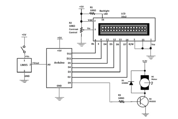
Listing 7. Temperature Controller Sketch
/* Converting LM35 Sensor data to Temperature
Sketch will take sensor data and convert it to volts then to temperature.
Volts and Temperature values will be displayed on serial monitor and LCD.
It turns ON a small dc motor when sensor temperature is greater than the threshold value.
Remixed sketch of ladyada's TM36 sensor tutorial
http://www.ladyada.net/learn/sensors/tmp36.html
Don Wilcher 03/17/12
*/
//LM35 Pin Variables
int sensorPin = 0;// The analog pin the LM35's Vout is connected to.
const int motorPin = 9; // the number of the motor pin

#include <LiquidCrystal.h>
LiquidCrystal lcd(12, 11, 5, 4, 3, 2);
/*
Initialize serial connection with the computer*/
void setup()
{
Serial.begin(9600); // Begin serial connection with the computer
lcd.begin(16,2);
analogReference(INTERNAL);
/* for Arduino Mega please use analogReference(INTERNAL1v1); */
pinMode(motorPin, OUTPUT);
}
void loop()
{
int reading = analogRead(sensorPin); // read data from LM35 using Arduino (A0) pin
float voltage = reading *5.0; // Convert sensor data to voltage
voltage /=1024.0;
Serial.print(voltage); Serial.println("volts"); // Print voltage on serial monitor
float temperatureC=((100*1.1*voltage)/1024)*100;
float temperatureF=(temperatureC*(9.0/5.0))+32; //Convert voltage to temperature
Serial.print(temperatureF); Serial.println(" degrees F");// Print Temperature in C
// display Temperature on LCD
lcd.setCursor(0,0);
lcd.print("Temperature=");
lcd.setCursor(0,1);
lcd.print(temperatureF); lcd.println(" degrees F ");
//DC Motor control
if(temperatureF >58){
digitalWrite(motorPin, HIGH);
}
else{
digitalWrite(motorPin, LOW);
}
delay(10);// print data every 10milliseconds
}
Further Discovery Method
The task presented in this chapter involves crafting a system block diagram for the temperature measurement controller. Supplementary endeavors encompass:
• Integrate an LED that responds to temperature thresholds, illuminating in tandem with the small DC motor’s activation.
• Substitute both the motor and LED with a piezo-buzzer to introduce audible temperature notifications.
• Swap the conventional 16×2 display for a 20×4 LCD screen.
• Exchange the DC motor for a vibration unit to observe its electrical behavior.

