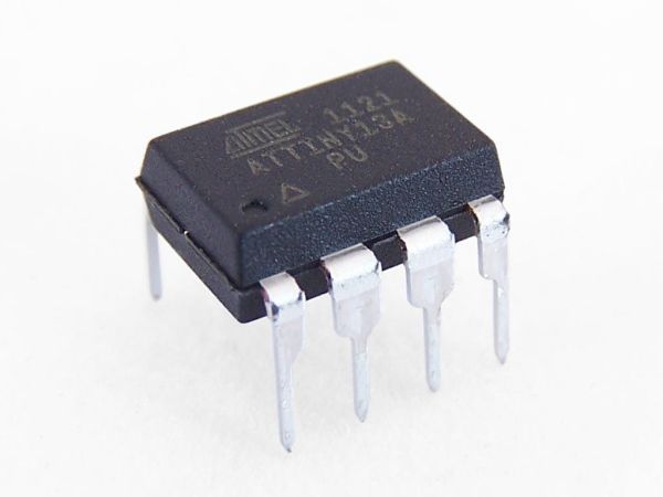
So there I was, browsing eBay, looking for some cheap deals on Atmel chips when i came across a pair of ATTiny13 chips for £2.50. I just had to have them! After all, how hard can it be?
I needed a small chip to read servo signals from a hobby RC Receiver and control a laser output.
Once they arrived it dawned on me that I actually had no idea how to program these little chips. Dom and I spent hours trying various ways of ATTiny programming we found online with no luck. It was only until he left I sat down at my computer and found Tekstop’s tutorial on ‘Tiny programming that I had any success. With a couple of modifications to his files you will be up and programming these low price chips in no time!
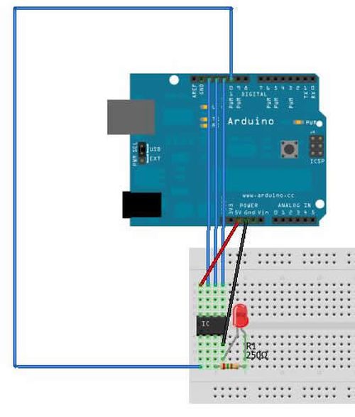
Connect your ATTiny13A to your arduino following the diagram below
Arduino pin 12 – ATTiny pin 6
Arduino pin 11 – ATTiny pin 5
Ardunio pin 10 – ATTiny pin 1
Arduino +5v – ATTiny pin 8
Arduino GNd – ATTiny pin 4
Optional:
GND – negative side of LED
ATTiny pin 3 – resistor (250 ohm) – positive side of LED
ATTINY13A Datasheet: http://www.atmel.com/Images/doc8126.pdf
Arduino ISP info: http://arduino.cc/en/Tutorial/ArduinoISP
Step 2: Setting up the IDE
- Open the arduino IDE and connect your Arduino
- Go to file > Examples > ArduinoISP
- Check you have the correct board & port selected (Tools > Board/Serial Port)
- Press the upload button
This will program your arduino board to be used as an ISP (in system programmer)
- Once complete, close the IDE
We now need to set up the IDE to recognise our ATTiny13A as an arduino compatible chip
- Download and extract this file: https://github.com/tekstop/attiny/tree/Arduino1
- Copy the folder “attiny” from the extracted ZIP to the /hardware/ folder in your arduino IDE installation directory
We then need to offset the clock speed (not a very elegant solution, but i’m working on it!):
- Open Hardware/attiny/boards.txt
- Scroll to the bottom of the file, this last few lines contains the data relevant to our chip
- Change “attiny13.build.f_cpu=9600000L” to “attiny13.build.f_cpu=1000000L”
This will correct delay times etc.
- Open the Arduino IDE again
- Go to Tools>Board and select “ATtiny13 (internal 9.6 MHz clock)”
Step 3: Programming
- Open the IDE
- Click File>Examples>Basic>Blink
- Change line 11 from “pinMode(13, OUTPUT);” to “pinMode(4, OUTPUT);”
- Change line 15 from “digitalWrite(13, HIGH);” to “digitalWrite(4, HIGH);”
- Change line 17 from “digitalWrite(13, LOW);” to “digitalWrite(4, LOW);”
- Click File>Upload using programmer
The IDE should now upload the sketch to your chip via your ArduinoISP programmer!
Once this is complete (~5 seconds) your LED should start blinking with a 1 second interval
Read more: Programming an ATTiny13A using Arduino & servo interpreter