
Construction
Mechanical structure
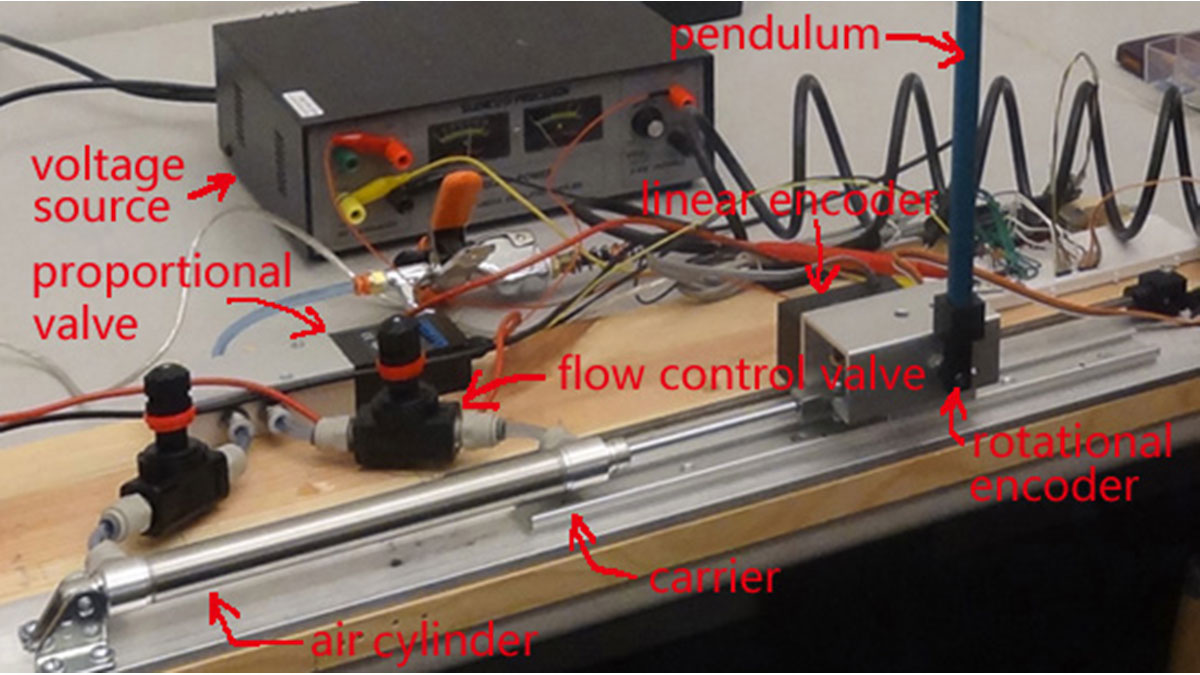 Compressed air comes from air compressor and goes in the proportional valve. Coming out from the proportional valve, there are two branches of air flow (one is compressor air, the other one is exhausted air) which connect to the air cylinder (pneumatic actuator). The pneumatic actuator connects to a cart (the aluminum box) where the pendulum is attached, and underneath the cart lies the carrier, which guides the cart along straight line. The rotational encoder is inside the cart, and its shaft is fastened throught the cart. The pendulum is attached to the shaft and is able to rotate 360 degrees. At the back side of the cart, a linear encoder is attached. For more detail please refer to VIDEO 1.
Note: the flow control valve is unused.
Control circuit board
Note that the “black green red yellow” in linear encoder diagram are just merely the color of wires. You might have different ones, but after watching VIDEO 3, it should be clear on how to use a linear encoder–the connection and programming are similar to rotational encoder. The operational amplifier should be connected to the +12 and -12 power supplies (not depicted). As noted above, if using separate power supplies, they must share a common ground.
Arduino
Visit arduino.cc to learn more.
Rotational encoder
The rotational encoder used in this project is S1-1250-250-I-N-D (more detail available in TABLE 1).
This encoder has 1250 counts per 360 degree (2*pi radians). Therefore, we have:
</center>And we could estimate cart velocity using</p>
<h3>Digital-analog converter and operational amplifier</h3>
<p><img decoding=)
Read more: Pneumatic Inverted Pendulum