Here is a project for locking and unlocking with a tilt sensor by tilting it in a defined sequence. It uses an accelerometer module to detect the tilt motion. If the sequence matches with the predefined motion sequence, the lock opens. You can build this lock for a briefcase, ballot box, portable cashbox or even as a door-lock using suitable mechanical arrangement.
Circuit and working
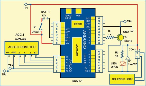
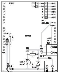
Fig. 1 shows circuit diagram of the sequential tilt-motion lock. The circuit is built around Arduino Uno board (Board1), accelerometer module (ACC.1), solenoid lock/electric strike and a few other components.
Arduino Uno board. Arduino is an open source electronics prototyping platform based on flexible, easy-to-use hardware and software. It is intended for artists, designers, hobbyists and anyone interested in creating interactive objects or environments.
Arduino Uno is a board based on ATmega328 microcontroller. It consists of 14 digital input/output pins, six analogue inputs, a USB connection for programming the on-board microcontroller, power jack, an ICSP header and a reset button. It is operated with a 16MHz crystal oscillator and contains everything needed to support
the microcontroller. It is very easy to use as the user simply needs to connect it to a computer with a USB cable, or power it with an AC-to-DC adaptor or battery to get started. The microcontroller on the board is programmed using Arduino programming language and Arduino development environment.
Pins A0, A1, A2, A3, A4 and A5 of Board1 are connected to pins ST, Z-axis, Y-axis, X-axis, GND and Vcc of the accelerometer module, respectively. Pin 10 of Board1 is connected to solenoid driver transistor through which the solenoid lock is connected.
Accelerometer module. An accelerometer is an electromechanical device that measures acceleration. The accelerometer module used here is based on ADXL335 triple-axis accelerometer from Analog Devices. The sensor has a full sensing range of ±3g.
The microcontroller in Board1 receives data at pins A1, A2 and A3 for z, y and x axes, respectively, from the accelerometer. This data is continuously compared by Board1 with predefined values for each axis. If the received sequence matches, Board1 unlocks the lock, which is either a solenoid lock or any other suitable magnetic lock. (We used a 12V electric strike for testing.) Glowing of LED1 indicates that the lock is open.
Software
The software for this project is written in Arduino programming language. The Arduino Uno is programmed using Arduino IDE software. ATmega328 on Arduino Uno comes with a boot loader that allows you to upload new code to it without the use of external hardware programmer. It communicates using the STK500 protocol. You can also bypass the boot loader and program the microcontroller through in-circuit serial programming (ICSP) header, but boot loader programming is quicker and easier. Select the correct board from ‘Tools → Board’ in Arduino IDE and burn the program (sketch) through standard USB port in the computer.
Construction and testing
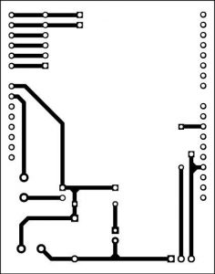
An actual-size (Arduino shield type), single-side PCB for the sequential tilt-motion lock is shown in Fig. 2 and its component layout in Fig. 3. Assemble the circuit on the recommended PCB to minimize assembly errors.
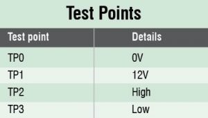
To test the circuit for proper functioning, switch on S1 and verify correct 12V supply for the circuit at TP1 with respect to TP0.
The neutral position of accelerometer module is parallel to the earth’s surface. The +Y and +X axes are marked on the accelerometer module. The default tilt sequence of this circuit defined in the source code is -X, -Y, -X, +Y, -Y. If the tilt sequence is correct, you can observe the glowing of an in-built LED (not shown here) connected to pin 13 of Arduino board. If you want to change the sequence, change it in the source code, recompile the program and burn into the microcontroller.
Read more: Sequential Tilt-Motion Lock