The next board I want to show you is the ADJD-S371 Color Light Sensor Evaluation Board from sparkfun. It emits light and analyses the reflected color spectrum. The board can be controlled via I2C. The sleep and xclk pins were not used in this example. I found a really nice tutorial describing how to connect the sensor to the Arduino. The example also provided the code to communicate with the sensor. I only had to change minor parts to fit my needs.
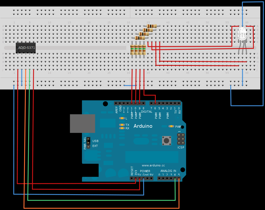
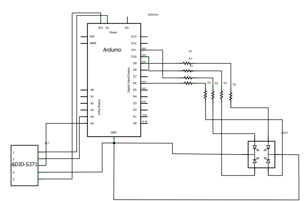
My basic setup looks a little bit different because I used a full color rgb LED with six pins. Two for ground, one for red, one for green and two for blue. I also used another schematic this time. What you see here is a software developed by the University of Applied Sciences Potsdam, here in Germany. The software is called Fritzing. You can design your circuit on a protoboard, convert it into a circuit diagram and even into a PCB layout for later manufacturing. It’s really nice and easy to use. Thanks for the tip Darsh!
As already mentioned I only changed the code from the tutorial a little bit to fit to my rgb LED.
//Configure gain here
//Higher numbers = less sencitive
// 0x00 through 0x0f
int redGain = 0x03;
int greenGain = 0x0;
int blueGain = 0x0f;
int clearGain = 0x01;

//Include the I2C Arduino library
#include

//7 bit I2C address of this sensor
#define I2C_ADDRESS 0x74
Read more: RGB Color Sensor on Arduino