Hi guys! So for my electronics class this year we were tasked with creating some kind of electronic gadget in order to demonstrate what we learned over the semester. Being a car-loving type of guy, I decided to get a cheap RC car and see in what ways I could hack it using an Arduino Leonardo I had leftover from lab. Having an infrared proximity sensor handy, I thought It would be nice to use the sensor to brake the car whenever It got too close to crashing into a wall. I’ll try to be as clear as possible in case you guys want to build something similar or in case it’ll help with one of your projects.
Step 2: The RC Car
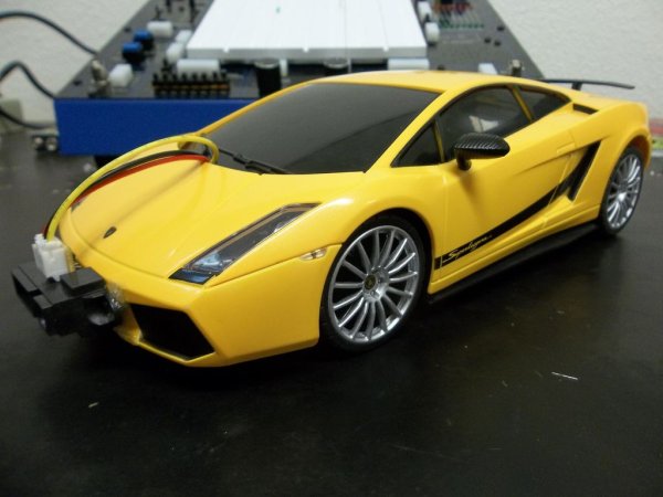
First off, I needed to get an inexpensive RC car I could hack. I didn’t want to get an expensive RC car in case I ended up ruining it over the course of my project so I ended up get this ~$20 car off of Amazon. Overall, there were no big surprises with this little car. The car required 4 AA batteries while the remote control it came with required a 9v battery, sadly the batteries were not included. Anyways, the next step was to open up the car and see what I was dealing with.
Step 3: Opening it Up
The Basics:
The car opened up without too much trouble, it just had a couple of screws on the bottom. Not knowing what to really to expect, I was kind of surprised to see how straightforward a setup the car actually employed. Essentially there are three main parts; the circuit board, the rear wheel drive DC motor, and the DC motor used for turning. I’ll discuss these in more detail in the next step.
The Remote Control:
I also opened up the remote control in order to see what type of input the car would be expecting. It also had a relatively simple set up, each control was basically dependent on two switches. For example, in order to control direction you’d press the switch corresponding to desired direction.
Since the car did not have variable speed or direction, I concluded that the car most likely dealt with digital logic. In other words, I was expecting to see the voltages used to either go HIGH or LOW.
Step 4: Analyzing the Insides
The Receiver:
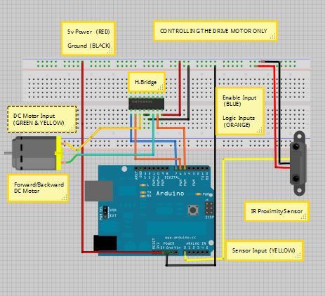
Once I got the car opened I tried to work out how the DC motors were being controlled. I decided to look up the chip placed in the middle of the circuit board to see exactly what it did. I discovered that it’s a receiver chip with four pins used to control both direction and speed. Flipping the circuit board over, I saw the pair of H-Bridges used to drive the DC Motors.They basically provide enough current to make sure the motors run. I’ll talk about H-Bridges a bit more later.
The Motors:
Looking at the circuit board closely, I saw that it had a power and ground connection going to the battery pack. The other connections went to the motors. Each motor was connected to the circuit board by two wires (one black, one red) and each wire was labeled depending on its function. For example one of the wires was labeled MF for Move-Forward (by my best guess).
The Overall Setup:
My best guess for how the car runs is that it essentially uses the receiver to process signals from the remote control. The receiver then sends a pair of HIGH or LOW signals to each DC motor.
Step 5: Measuring Voltages
Looking at the Receiver:
To begin I measured the voltages coming out of the receiver’s pins as I used the remote control. When a pin would go HIGH the voltage on it would be approximately 3.40 volts. When the pin went LOW it would be at about zero volts. These voltages are within the range necessary for the Arduino to correctly read them as HIGH or LOW.
Looking at the Motors:
I then measured the voltages on the connections going to the DC motors. When input to the motor went HIGH the voltage would range from 4.80 to 5.00 volts. And of course, when the input was LOW the voltage was about zero.
Read more: RC Car Anti-Crash System Using Arduino