 Multifunction_Digital_Thermometer.zip
Step 1: Gather Materials
To build the digital thermometer you will need:
– Wire
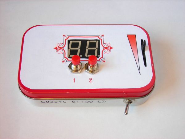
– Altoids tin
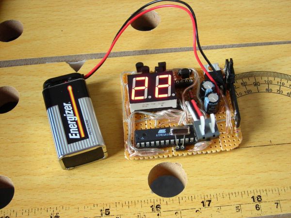
– Breadboard
– Variable Resistor
– Dual-digit Common Anode 7 Segment Display
– 4 2N2222 Transistors
– 2 220 k ohm Resistors
– Thermistor(preferably linear output)
– 2 Momentary Push Buttons
– 2 2.2 k ohm Resistors
– 5 volt Regulator
– 2 Leveling Capacitors for the Power Supply (I used 220 uF)
– Power Switch
– ATMEGA168 Microcontroller
– 16 MHz Crystal
– 1 k ohm Resistor
– Printable Label (Larger then the front of the Altoids tin)
– Sockets (any you think you may need)
Needed tools:
– Soldering iron
– Desoldering Pump (optional)
– Wire Stripper (optional)
– Wire Cutters
Step 2: Start Building

Before you start soldering it is probably best to first cut the breadboard to the final size and arrange all of the larger parts on the board (as seen in the 2nd image below). Don’t forget to allow room for the buttons above the board and a power button off to the side.
It should be noted that in the schematic that R5 is a comparison resistor for the thermistor, and it might be included in your thermistor, so you should check your data sheet for how to implement your specific thermistor.
 Thermometer.doc110 KB
 Thermometer.dwg985 KB
Step 3: Calibrate the Thermistor
To calibrate the thermistor, you need to take readings from the microcontroller at different temperatures (the more the better).
I have attached the hex file to be loaded into the microcontroller’s flash to display the analog input from the thermistor. If it reads with a line in the output, it is because the thermistor input is too high to be displayed on two digits (example the output -5 could be from 155 to 105).
The points should then be plotted in excel as a scatter plot, not connected by lines (for an example see my temperature readings attached below).
You then need to right click the data points on the graph and click “Add Trendline”.
Next choose the type of equation that is closest to the apparent line created by the sample points (I used a linear equation because my thermistor is made to have a linear output). Next click the “options” tab and select “display equation on chart” and click OK. This equation should be entered in the place of the formula in the source code, where x is “analogRead(tempPin)”. The spot to do this is indicated in the source code(found in the intro).
Read more: Multifunction Digital Thermometer using an Arduino