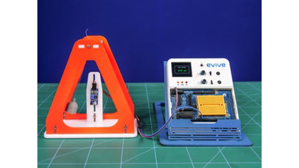
Calculating on paper is never an easy job. And when it comes to formulas with sub-formulas of their own, it is nothing short of a nightmare! Take the case of a simple pendulum, which has a variable with a formula of its own.
 What if there was a way to replace these scary calculations with a simple computer program?
You guessed it right! With the help of evive, an IR sensor, a computer program, and little DIYing, you can easily find out the time period of the pendulum in a matter of seconds! So, what are you waiting for?
Let’s get into it right away!
Step 1: Things You’ll Need:
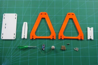
- evive
- IR Sensor
- Thick Cardboard
- M3 bolts of length 20 mm X 7
- M3 bolts of length 08 mm X 1
- M3 nuts X 8
- Male to Female Jumper Cables
You can also buy the evive Starter Kit , as the above components and even more, are found in it. Also. there are lots of projects listed on Instructables which are made with the help of it.
Step 2: Cutting the Layout
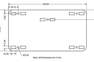 Cut out the cardboard according to the dimensions given:Tip
Step 3: Attaching the Sensor Holder Plate
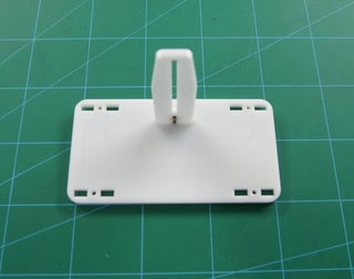 Take the base piece i.e, the piece of size 160 x 85 mm. Now, take the smaller piece of dimension 30 x 95 mm which holds your sensor and attach it to the base plate using M3 bolts of 20 mm and M3 nuts.
Step 4: Completing the Frame
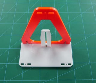
- Take the piece of size 162 x 150 mm and attach it to the base using M3 bolts of 20 mm and M3 nuts.
- Similarly, take the other piece of the same size and fix it using M3 nuts and bolts to the base.
- Now, take the last Acrylic piece of size 34 x 75 mm and attach it between the gaps of the two large pieces using M3 nuts and bolts. On this plate, we will be attaching the bob of the pendulum.
The base assembly is ready. All we need to attach is the Sensor and the bob which is a small weight attached to the string at its end.
Step 5: Attaching the Sensor
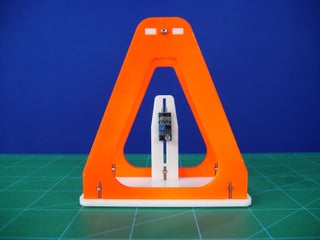 We will start fixing the sensor on the sensor holder plate in the vertical gap using M3 bolts of 8mm length and M3 nuts.
Step 6: Pendulum’s Bob
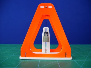 Once it is attached, it’s time for the last part of the assembly, the bob. Bob is nothing but a small weight attached to the string at its end. The bob we used here is a 3D printed one. You can make it using any heavy material or even clay.
Now, the free end of the string is passed through the hole on the upper horizontal piece and its length is thus adjusted according to the height required.
Make sure that the pendulum always remains in the same line as that of the sensor’s LEDs.
Now, the assembly of the simple pendulum is thus complete.
Want to make more 3D printed stuff? Now, whatever you design can come to life. Own a 3D printer now!
Step 7: Circuitry
- GND to GND of evive
- VCC to +5V
- OUT to Digital Pin 2
Read more: Measuring Time Period of a Pendulum Using IR Sensor