In this instructable, I will show you how to make a sensor that will light up more lights the closer you are to it.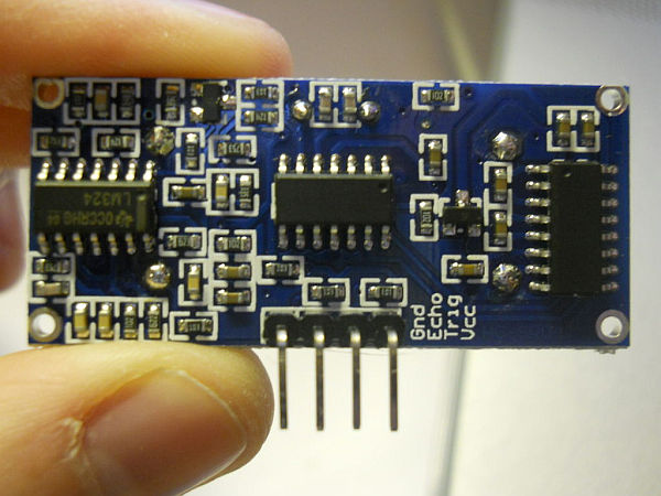
Step 1: Placing The Electronics
This step will show you where and how to place the electronics on the breadboard
Materials:
6-220 ohm resistors
3 green LED’s
2 yellow LED’s
1 red LED
Ultrasonic ping distance sensor
Breadboard
First, place the distance sensor on one end of the breadboard so that none of the pins are connected (usually parallel to the outside rails).
Then place the LED’s in the order from Left to Right : Green, Green, Green, Yellow, Yellow, Red
Each LED should have the long lead facing the same way. Mine are on the left side.
Next, connect a resistor to the short leg of each LED and to the inside rail of the breadboard.
Once that is done, move on to the next step.
Step 2: Adding The Wires
In this step, I will show you how to put the wires into the breadboard to connect to the arduino.
Materials:
Wire
First, Take the pin on the sensor marked VCC. Connect that to the outside rail of the breadboard
Then take the pin marked GND and connect that to the inside rail of the breadboard.
The pins marked TRIG and ECHO can be placed in another column to combine them. Then, add a wire connected to the same column on one end but not the other. This will later be connected to that arduino, but not in this step.
Connect a wire to the long pin on each LED. These will later be connected to the arduino, but not in this step.
Finally, connect a wire to each of the rails on the breadboard. These too will later be connected to the arduino, but not in this step.
Step 3: Connecting to the Arduino
In this step I will show you how to connect the wires from the breadboard to the arduino.
Materials:
Arduino
Breadboard with parts
First, take the wire from the outside rail and connect it to the 5V supply o the arduino
Then take the wire from the inside rail and connect it to the GND input
Take the ECHO and TRIG combined wire and connect it to pin 12 on the Arduino
Take the wires from the LED’s and connect them to pins 2-7 on the Arduino in the same order that the LED’s are on the breadboard.
Step 4: The Code
Materials:
Arduino +Breadboard + Electronics
Computer
USB cable to connect arduino & computer
Arduino Environment
Here is a video of the whole thing n action
Copy and paste this code into the processing environment.
Read more: How to make A light-up distance sensor