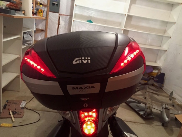
As a motorcycle rider, I’m all too familiar with being treated like I’m invisible on the road. One thing I always add to my bikes is a top box which usually has an integrated light. I recently upgraded to a new bike and bought the Givi V56 Monokey box since it had lots of space for items. This box has a spot for a factory light kit which consists of two strips of LEDs for each side. The problem is this kit is about $70 and only does brakes. There is an aftermarket kit that probably does similar things and might be a bit easier to install, but your price goes up to $150. Being a resourceful person and looking for an excuse to try out the addressable LED strips, I decided to make an integrated system that not only would have brake lights, but running lights (on whenever moving), turn signals, and hazard lights. Just for the heck of it, I even added a startup sequence…. because I could. Note that this took a lot of work to do though I had a lot of things to figure out. Despite the work, I’m rather happy with how this turned out. Hopefully this ends up being useful to someone else.
The basic operation of how this system works is the Arduino unit looks for signals on the pins: brake light, left turn light, and right turn light. In order to read the 12 volt signal from the motorcycle, I used optoisolators to convert the 12V signal to a 5V signal that Arduino can read. The code then waits for one of these signals then outputs the commands to the LED strip using the FastLED library. That’s the basics, now to get into the details.
Supplies:
These are the things that I used because for the most part I already had them lying around. Obviously, they can be exchanged out as needed:
- Arduino – I used a nano for size considerations but you can use whatever you feel like as long as you have five pins to use.
- 5V regulator – I used an L7805CV that was capable of 1.5 amps. This project will use 0.72 amps for the LEDs plus the power for the nano, so 1.5 works great for this project.
- Capacitors – you will need one 0.33 uF and one 0.1 uF for the voltage regulator to operate properly.
- 3x optoisolators – to do the signal conversion from 12V to 5V. I used PC817X type which only have four pins which is all we need.
- Resistors – you will need two types, three of each type. The first needs to be enough to reduce the current through the optoisolator IR LED. You will need at least 600 ohm, but 700 would be a better idea to handle changing voltages on the motorcycle. The other needs to be somewhere between 10k and 20k for a quick signal on the other side of the optoisolator.
- Prototype board – I had some that were small enough to fit inside a small project box with a slight amount of trimming.
- Project box – big enough to fit the components, but small enough to be easy to fit.
- Wire – I used Cat 6 ethernet wire because I had a lot of it sitting around. This has eight wires all color coded which helped with all the different connections and was a large enough gauge to handle the current draws.
- Plugs – anywhere you want the system to be easily removable. I used a waterproof plug to allow the top box to be removed and to handle any rain or water that gets on it. I also needed smaller plugs for the LED strips so I didn’t have to drill large holes.
- Zip ties and zip tie adhesive mounts to hold everything in place.
- Shrink wrap to tidy up the connections.
Step 1: Building the Circuit
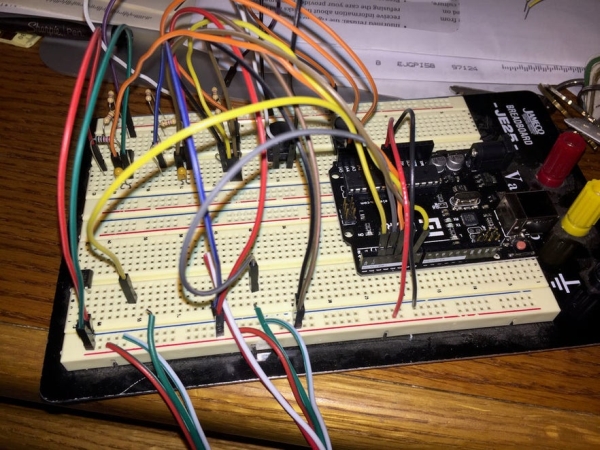
Obviously, if you’re following my build, you won’t have to go through the amount of testing I did. First thing I did was to make sure my code worked and I could properly get a signal from the optoisolators as well as properly control the LED strips. It took a moment to figure out how best to attach the signal pins to the isolators but through trial and error I found the right orientation. I just used a standard prototype board since I was only building one and figuring out a trace pattern would have taken more time than it was worth. The top part of the circuit board looks great, but the bottom does look like a bit of a mess, but at least it’s functional.
The basic design starts with inputting the 12V power from a switched source (a wire that is only on when the motorcycle is on). A wiring diagram can really help to find this wire. This is fed into one side of the voltage regulator. A 0.33 uF capacitor ties this input to the ground on the voltage regulator which then feeds back to the ground on the motorcycle. The output of the voltage regulator will have a 0.1uF capacitor tied into it to ground. These capacitors help to smooth out the voltage from the regulator. If you can’t find them in the picture of the circuit board, they are underneath the voltage regulator. From there, the 5V line goes to the Vin on the Arduino, to the power pin that will feed the LED strips, and two the Source side of the optoisolator that will feed into the Arduino pins providing the needed 5V signal.
As for the optoisolators, there are two sides: one with an IR LED and the other with a transistor with and IR detector. We want to use the IR LED side to measure the 12V signal. Since the LED has a forward voltage of 1.2V, we need a current limiting resistor in series. 12V – 1.2V = 10.8V and to run the LED at 18 mA (I always like to run less than 20 mA for lifetime reasons), you will need a resistor of R = 10.8V/0.018A = 600 ohm. Voltages on vehicles also tend to run higher, potentially up to 14V, so it’s better to plan for that, which is about 710 ohm, though 700 would be more than reasonable. The output for the LED side then feeds back to ground. For the output side of the optoisolator, the input will use the 5V signal from the regulator then the output will connect to another resistor before going to ground. This resistor just needs to be around 10k – 20k ohm, at least that’s what my datasheet showed. This will give a quick signal measurement since we’re not dealing with a noisy environment. The output to the Arduino pin will come off between the resistor and the output of the optoisolator so that when the signal is off the pin is low and when the signal is on the pin is high.
The LED strip lights have three wires associated with them: Power, ground, and data. Power needs to be 5V. This project uses 12 LEDs total (though I have more LEDS on the strips but I’m only using every third LED) and each takes 60mA when white light is used at full brightness. This gives a total of 720 mA. We’re well within the output power for the voltage regulator, so we’re good. Just make sure that the wire is a large enough gauge to handle the power, I used 24 gauge Cat 6 ethernet wire. Ethernet wire was something that I had sitting around and it has 8 color coded wires so it worked out well for this project. The only wires that then need to go to the topbox itself is the power and ground (which both get split between the strips) and two data lines (one for each strip).
The rest of the wiring is connecting to the pins on the arduino and feeding it power. The pins that were used for this project were the following:
- Vin – connected to 5V
- Gnd – connected to ground
- Pin2 – connected to Left strip data line
- Pin3 – connected to Right strip data line
- Pin4 – connected to Brake signal from the optoisolator
- Pin5 – connected to Left turn signal from the optoisolator
- Pin6 – connected to Right turn signal from the optoisolator
Step 2: Wiring and Installing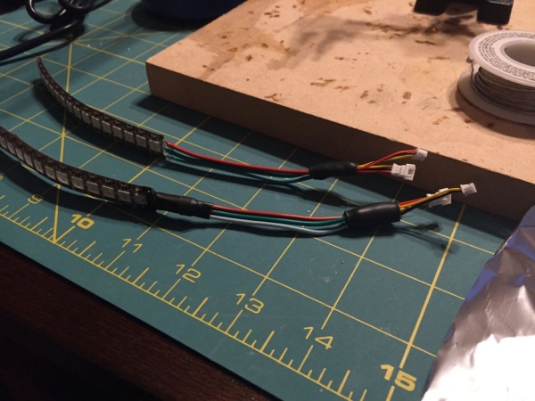
Once the circuit is built, the time comes to actually wire this into place. Using your wiring schematic for your bike, you will need to locate the following:
- Switched power supply
- Ground
- Brake Signal In
- Left Turn Signal In
- Right Turn Signal In
For mine, there was a single plug that had all of these on it, so I just used that. With enough time, I might have been able to find the same plug style and just make a plug in module, but I didn’t, so I just removed the insulation in places and soldered the new wire to it. I used plugs on these spliced connections so that I could remove the rest should I ever need to in the future. From there I placed the Arduino, which is now in a sealed project box, under the seat where I attached it. The output cable then runs along the rack frame to a waterproof plug, then enters the box and runs along the back to the lid where it splits for each side. The wires run along the inside of the lid to the point where the connections for the LEDs are at. The wire is help in place using zip ties attached to Outdoor grade zip tie mounts with an adhesive backing. You can find these in the cable installation section at a home improvement store
I used two mini JST plugs on the LED strips because I needed a plug small enough to go through a hole of minimum diameter and because I wanted to make sure there was enough wire to handle the current requirements. Again, it may have been overkill and I didn’t have any small plugs with three wires handy. The hole in the box for the light strip wires to pass through were sealed up to keep water out. As for positioning the LED strips, because there is a slight mismatch in spacing (there was about 1 – 1.5 mm difference in spacing between the holes in the reflector and the LEDs) I positioned them so that they would split the difference between the LED and the hole as much as possible. I then used hot glue to tack them in place and sealant to fully seal the area. The LED strips themselves are waterproof, so no issue if they get wet. Although it seems like a lot to install, this makes the system easier to remove in the future or replace parts are needed because it could happen.
Step 3: The Code
My source code should be at the beginning of this Instructable. I always comment my code heavily so it’s easier to understand later on. Disclaimer: I’m not a professional code writer. The code was written in a method that was easier to get going first and some improvements were made, but I know it could be more refined. I’m also using a heavy amount of the delay() function for timing which is not as ideal. However, the signals that the unit is receiving are not fast signals in comparison, so I still felt justified to keep them over using something like millis(). I’m also a very busy father and husband so spending time to improve something that will ultimately not change the function isn’t high on the list.
For this project, only one library is required which is the FastLED library. This has all the code for controlling the WS2811/WS2812B type LED strips. From there, I’ll cover the basic functions that will be used.
The first other than the standard definitions is to declare your two strips. You will use the following code for each strip:
FastLED.addLeds<WS2812B, 2,RGB>(leds[0], NUM_LEDS);
This line of code sets up Pin 2 defines this strip as strip 0 with the number of LEDs defined by the constant NUM_LEDS, which in my case is set to 16. To define the second strip, the 2 will become 3 (for pin3) and the strip will be labeled strip 1.
The next line that will be important is color definition.
leds[0][1] = Color_high CRGB(r,g,b);
This line of code is used though in different looks (most of my use a constant). Basically, this code sends a value to each of the LED channels (red, green, blue) that defines each brightness. The brightness value can be defined by a number 0 – 255. By changing the level of brightness for each channel, you can define different colors. For this project, I want a white color to keep the light as bright as possible. So the only changes I do is to set the brightness level the same across all three channels.
The next set of code is used for individually lighting each light. Note that for each strip, each LED has an address that starts at 0 for the one closest to the data line connection all the way up to the highest number LED you have minus 1. Example, these are 16 LED strips, so the highest is 16 – 1 = 15. The reason for this is because the first LED is labeled 0.
for (int i = NUM_LEDS-1; i > -1; i = i - 3) {    // This will change the light for every third LED going from the last to first.<br>    leds[0][i] = Color_low;                      // Set strip 0 LED color to the chosen color.
    leds[1][i] = Color_low;                      // Set strip 1 LED color to the chosen color.
    FastLED.show();                              // Show the set colors.
    leds[0][i] = CRGB::Black;                    // Turn off set color in prep for next color.
    leds[1][i] = CRGB::Black;
    delay(150);
  }
  FastLED.show();				 // Show the set colors.
The way this code works is that a variable (i) is used within a for loop as the LED address which is then referenced to the full number of LEDs (NUM_LEDS). The reason for this is that I want the lights to start at the end of the strip rather than the beginning. The setting is output to both strips (leds[0] and leds[1]) then a command to show the change is issued. After that this light is turned off (CRGB::Black) and the next light is lit. The Black reference is a specific color in the FastLED library so I don’t have to issue 0,0,0 for each channel though they would do the same thing. The For loop advances 3 LEDs at a time (i = i-3) since I’m only using every other LED. By the end of this loop, the light sequence will go from one LED to the next with only one lit per strip, sort of a Knight Rider effect. If you want to keep each light lit so that the bar builds, you would just remove the lines that turn the LEDs off which happens in the next set of code in the program.
for (int i = 0; i < dim; i++) {                 // Quickly fade lights to running light level.  <br>    rt = rt + 1;
    gt = gt + 1;
    bt = bt + 1;
    for (int i = 9; i < NUM_LEDS; i = i +3) {     // This will light up the last three lights for the position light.
      leds[0][i] = CRGB( rt, gt, bt);             // Set strip 0 LED color to the chosen color.
      leds[1][i] = CRGB( rt, gt, bt);             // Set strip 1 LED color to the chosen color.
    }
    FastLED.show();
    delay(3);
  }
The last example of code that I use for the LEDs is a fade loop. Here, I use temporary slots for the brightness for each channel (rt, gt, bt) and increment them by 1 with a delay between each showing to achieve the appearance I want. Also note that this code is only changing the last three LEDs as this is fading in the running lights so i starts at 9 rather than 0.
Read more: DIY Givi V56 Motorcycle Topbox Light Kit With Integrated Signals