In this project we are going to be making something super useful! It is a wireless keyboard that you can connect to your PC and assign each button any shortcut or key sequence you want! I have made it in a way where you can customise the keyboard to meet your exact needs, for example, the number of buttons you want and easily configure the buttons to do whatever you want. It is also made to be very efficient to run on a coin battery for a long time! I have also made a video showcasing this keyboard and I go through each step, so check that out if you are interested. It’s actually a very nice and simple project to do. So let’s get into it!
Supplies
 Before we get to the components you will need for this project, I think it is a good idea to just explain how this keyboard will work so you can fully understand what is going on. The idea is that we will have a transmitter side and a receiver side. The transmitter is the side where all the buttons are connected to, and the receiver side is connected to your computer via a USB connection. The way we will communicate between the transmitter and receiver wirelessly is by using a radio signal. This is illustrated in the image above. This should now give you an idea how the keyboard works.
Now for the components/supplies!
We need two micro-controllers, one for the transmitter side, and one for the receiver side.
- For the transmitter, we will be using the Attiny84 micro-controller. It’s super small, inexpensive, can be used just like any Arduino, and most importantly, it consumes very little current, which is needed because the transmitter side will run on a battery, and we want it to last as long as possible of course!
- For the receiver side, we will be using the Pro Micro, you can pretty much use any Arduino for this, however, it has to have HID support. I recommend using the Pro Micro.
Now to communicate between these two micro-controllers, we said we will be using a radio signal, and to get that we will use the nRF24L01 radio module. You need two of these, one for each micro-controller.
To power the Attiny85, we need a battery, I have chosen the CR2450 coin battery, it provides 3 V and has a capacity of 500 mAh, which is great for such small size. You will also need its battery holder.
Because the voltage of a battery is not stable and goes down overtime, we will need to use a voltage regulator to keep the voltage the same no-matter what voltage the battery is at. The voltage regulator used is the MCP1700 3.3V, with two capacitors (100 or 1000 µF and 100,000 pF) soldered directly on it to keep the signal smooth and deal with voltage spikes.
You will also need some buttons! You can pretty much use any kind of buttons you want, but since we are first going to make it on the breadboard, use the normal breadboard push buttons to start with. After we have got it all working on the breadboard then we can get all fancy and use proper buttons! For now just the normal breadboard push buttons are perfect.
That’s all the components you will need! As you can see, this will be a very simple project but very very useful and practical.
Here is just a list of all the components without any explanation for convenience.
- Attiny85
- Pro Micro
- nRF24L01 (x2)
- CR2450 coin battery (or any battery), and its battery holder.
- MCP1700 3.3V voltage regulator, with two capacitors soldered on it (100 or 1000 µF and 100,000 pF).
- Buttons (Any kind).
Step 1: Wiring for the Transmitter Side
 First, let’s start off by creating the wiring for transmitter side, simply follow the diagram above of the breadboard wiring.
Step 2: Wiring for the Receiver Side
 Then lets do the wiring for the receiver side, again, just follow the diagram above for the breadboard wiring. Make sure you double check and confirm all the connections.
Step 3: Transmitter Code
 For the code, it’s very simple, you only have to make a few changes to meet your needs. All the code can be found in this repository.
You will need to install two libraries using the Arduino library manager in the Arduino IDE:
- RF24 by TMRh20.
- Button by Michael Adams.
For the transmitter code, you only need to make two changes:
- The MAX_SHORTCUT_KEYS variable, this is the maximum number of characters a keyboard shortcut/sequence can be. This is specified so only the required number of bytes are sent through the radio signal. For example, if you are only going to use shortcuts that are maximum 3 characters long (e.g. CTRL + SHIFT + R), then MAX_SHORTCUT_KEYS should be 3. The more characters you need, just increase this variable.
- The BUTTONS_INFO array. I suggest looking at this array in the image above while reading this. Each button element is made up of two values, the first is the pin number the button is connected to your micro-controller. The second is a string of characters seperated by spaces. The characters are represented by their decimal/int values, which can be found here and here. So lets say for example, you have a button connected to pin 12 on your micro-controller, and you want it to copy when you press it (CTRL + C). So you would lookup the decimal values for those keys using the links provided, the CTRL key is 128, and the “c” key is 99. So your entry for that button in the array will be {12, “128 99”}. This way, you can very easily assign each button to do whatever you want (Side note: Since we are only using two characters in the string, then our MAX_SHORTCUT_KEYS will be set to 2 in this case).
That’s all the changes you need to make. Now you just need upload this code to the Attiny. You can find instructions on how to upload code to the Attiny in the same repository.
Step 4: Receiver Code
 For the receiver code, you only need to make one simple change, and that is to ensure the MAX_SHORTCUT_KEYS variable matches to what it is in the transmitter side. Then just simply upload the code to the micro-controller (Pro Micro).
Step 5: Breadboard Demo
 Now, it’s pretty much all done. Connect the battery to the transmitter side and connect the receiver side to the computer via the USB connection, and now you should be able to press your buttons and it will perform exactly what you programmed the buttons to do! You will also notice that there is no noticable delay at all, which is great!
Step 6: Battery Consumption
 Something to share as well, is what the expected battery life will be for this keyboard! This is all summarised in the image above. So we can see that the total current consumption is 1.284 mA, which means if the keyboard is always on, we will get a battery life of 16 days. However, in practise, like any wireless device, we switch it off when not in use, so this means that we should at least get 30 days from just a single CR2450 coin battery, which is actually pretty amazing!
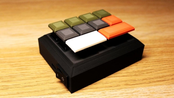
Step 7: 3D Printing and Proper Buttons
 Now, if you have a 3D printer, you can either use the design I have already made (which you can find in the repository) or make your own design for as many buttons as you want.
I ended up using the Attiny88 micro-controller for the transmitter side as it has 28 pins, because with each button you add, the more pins you need. For the buttons I used MX Cherry switches.
Step 8: Done!
 And just like that, you have created your own custom wireless keyboard, which will proudly sit on your desk!
Read more: Custom Wireless Keyboard! (Arduino)