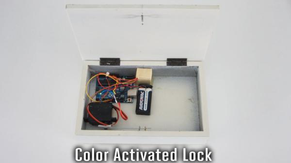
There are a lot of ways that you can activate an electronic lock. You can use passwords, radio signals, or even voice commands. In this project, I am going to show you how to make a lock box that opens and closes based on color recognition.
With a color recognition lock, anything can be a key. You can set the lock to recognize the color of a cereal box, or the cover of your favorite book. You could even use pictures on your phone as the key. With so many different color combinations, a color lock is also very difficult to break into.
Step 1: Watch the Video
Here is a video walkthrough of the project.
Step 2: Background: How Color Recognition Works
White light is composed of all the colors of the rainbow. When it hits a surface, some of the colors are absorbed and some of the colors are reflected. The reflected colors are what we perceive as the color of that object.
In order to measure and quantify color with an electronic circuit, you need to measure the intensity of the various wavelengths of light that are reflected off the surface. The easiest way to do this is to shine a single color of light on that surface at a time, and then measure the total intensity of the reflected light.
At a minimum, you need to use each of the primary colors of light (Red, Blue and Green). So a basic color sensor will have a red LED, a blue LED, a green LED, and light sensor such as a photoresistor. By measuring the reflected light for each color, you can calculate the color of the object.
Step 3: Materials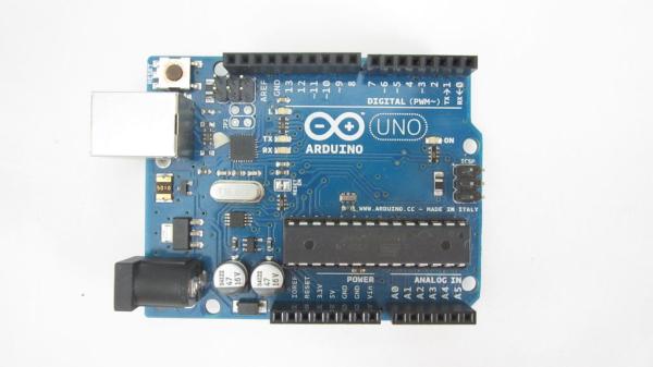
Here are the materials and tools that you will need for this project.
Materials:
Arduino microcontroller
Wooden Box
Full Color LED (or separate red, blue and green LEDs)
Photoresistor (light dependent resistor)
2 x 51 ohm resistor
120 ohm resistor
100 kohm resistor
Perfboard (or other printed circuit board)
Servo motor
Jumper wires
Paper or cardstock
Tape
Paperclip
3 x Eye screws
Wood Spacers
9V battery
9V battery connector
Tools:
Soldering Iron
Knife
Hot Glue Gun
Pliers
Drill and bit set
Small wood saw
Step 4: Construct the Color Sensor
The color sensor has two basic parts. There are LEDs that emit red, blue and green light. There is also a light sensor that detects the intensity of the light.
For the LEDs I used a single full color LED that can emit all three colors. This is basically four LEDs in one. It has four leads. Each color has its own lead for its cathode (negative side). The forth lead is a common anode (positive lead) for all three LEDs. I used markers to color code the leads to help me keep track of them.
For the light sensor I used a photoresistor (light dependent resistor). This is a resistor that changes its resistance depending on how much light hits the front face.
In order to use these parts as a color sensor, you just need to connect a couple of resistors and wires. Each color LED needs its own series resistor to bring the voltage down to the appropriate level. I used a 51 ohm resistor for the blue lead, another 51 ohm resistor for the green lead and a 120 ohm resistor for the red lead. The photoresistor also needs a series resistor so that you can make a voltage divider and measure the output of the sensor. The value of this resistor will depend of the specific photoresistor that you are using. For mine, I used a 100 kohm resistor. I soldered all the parts onto a perf board to hold them together.
Step 5: Add a Light Shield Around the Color Sensor
We want the photoresistor to only measure light from the LEDs. So we need to block out as much ambient light as possible. To do this, I made a simple light shield for it.
Take a small piece of card stock and fold it so that it can wrap around the sensor. Cut slots in the bottom of the card stock to make tabs that can fold under the circuit board. Wrap the card around the color sensor and tape all the sides to hold it in place. This won’t block 100 percent of the light but it will drastically improve the performance of the sensor.
Step 6: Connect the Color Sensor to the Arduino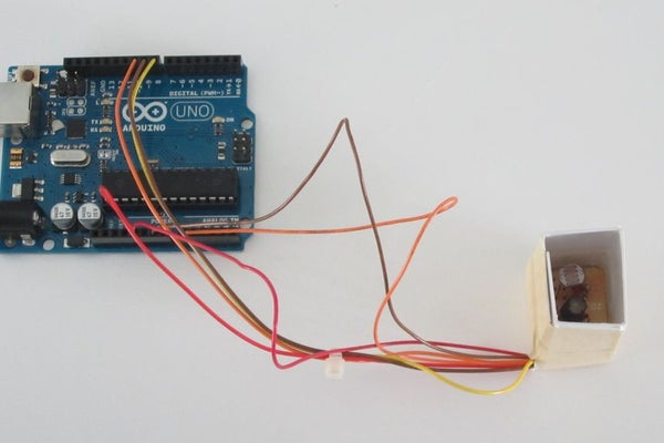
Now you are ready to connect the sensor to your Arduino. First connect the LED. Connect the three cathode leads of the LED to digital pins 8, 9, and 10. Then connect the common anode of the LED to the 5V pin.
Next connect the light sensor. Connect the free lead of the photoresitor to the GND pin. Connect the free pin of the fixed resistor to the 5V pin. Lastly, connect the center pin between the two resistors to the analog input pin 0.
Step 7: Attach a Servo to the Arduino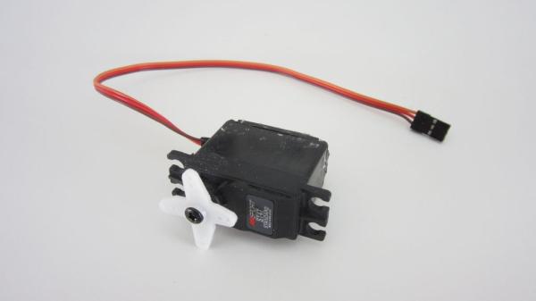
I decided to use a small servo motor to open and close the lock. This can be connected directly to the Arduino. To attach it, connect the brown wire on the servo to a GND pin on the Arduino. Then connect the red wire on the servo to the 5V pin on the Arduino. Lastly connect the orange wire on the servo to digital pin 6 on the Arduino.
Now when you run the code, you should see the servo actuate whenever you place the appropriate color in front of the senor.
Step 8: Sample Arduino Code
//Here is some sample Arduino code that you can use.
//You will need to adjust some of the values to calibrate it to your setup.
#include
Servo myservo; // create servo object to control a servo
int GreenLedPin = 8; // Green LED connected to digital pin 8 int RedLedPin = 9; // Red LED connected to digital pin 9 int BlueLedPin = 10; // Blue LED connected to digital pin 10
int analogPin = 0; // photoresistor connected to analog pin 0 int GreenVal = 0; // variable to store the value of reflected Green light int RedVal = 0; // variable to store the value of reflected Red light int BlueVal = 0; // variable to store the value of reflected Blue light
int GreenRedDifference = 0; int GreenBlueDifference = 0;
int GreenRedLockCode = -31; // lock value int GreenBlueLockCode = 47; // lock value
int sensitivity = 5; // set sensitivity of the color sensor
void setup() { myservo.attach(6); // attaches the servo on pin 6 to the servo object
Serial.begin(9600); // setup serial pinMode(GreenLedPin, OUTPUT); // sets the digital pin as output pinMode(RedLedPin, OUTPUT); // sets the digital pin as output pinMode(BlueLedPin, OUTPUT); // sets the digital pin as output} } void loop() { delay(1000); digitalWrite(GreenLedPin, HIGH); // sets the Green LED off digitalWrite(RedLedPin, HIGH); // sets the Red LED off digitalWrite(BlueLedPin, HIGH); // sets the Blue LED off delay(1000); // waits for a second digitalWrite(GreenLedPin, LOW); // sets the Green LED on delay(100); GreenVal = 1023 – analogRead(analogPin); // read the input pin Serial.println(); Serial.print(“Green “); Serial.println(GreenVal); // debug value delay(1000); // waits for a second digitalWrite(GreenLedPin, HIGH); // sets the Green LED off delay(1000); // waits for a second
digitalWrite(RedLedPin, LOW); // sets the Red LED on delay(100); RedVal = 1023 – analogRead(analogPin); // read the input pin Serial.print(“Red “); Serial.println(RedVal); // debug value delay(1000); // waits for a second digitalWrite(RedLedPin, HIGH); // sets the Red LED off delay(1000); // waits for a second
Read more: Color Recognition Lock