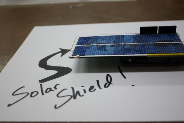
This instructable is a basic version of Bley Joel’s (“It’s nine o’clock on a Saturday, the regular crowd shuffles in”) Solar Shield, and it should work for most arduinos. I’ve tested it with SparkFun’s Arduino Pro, and the new Leonardo.
Myself and the other Solar Pocketeers* are actually waiting for a new set of PCBs for an advanced version of this solar shield to arrive on Wednesday Sept 5 (in 4 days), but being impatient, here is a version of a direct-power solar shield that doesn’t require a PCB. You read that right — PCB-free shields! Any rigid backing — a thin piece of acrylic, a breadboard, an old empty circuitboard, a discarded Muji plastic pencil holder, even– any of these will work as the backing for the shield. Some drill holes, a bit of copper tape, and some supergluing and you should be on your way to a lovely solar shield that is sure to win you lots of friends. And a minor amount of lost fingerprint fidelity.
I’ve included a basic set of templates for cutting the backing and the copper tape (for the two electrical connections you will need to make between the pins of the shield and the positive and negative of the series-connected solar cells (also known as “solettes”, since they are tiny and cute lasercut solar shards)). Those two items and a supply of solettes and you can be off to the solar races.
Time to complete: an hour
A wee bit of soldering required
Difficulty level: Pretty easy, but you will likely break 4-5 solettes at first. It requires a bit of a delicate touch.
Usefulness: To be determined
*First, I promise to never use the term “Solar Pocketeers” again — but better me than someone else. Second, this is the 6th entry in the Solar Pocket Series of projects that Alex (this guy) and I are posting over the coming weeks. For more about Solar Pocket Factories and DIY solar check out our in-progress Kickstarter campaign (Aug 15 – Sept 14): http://www.kickstarter.com/projects/alex9000/the-solar-pocket-factory-an-invention-adventure/posts/303802
Here’s what it’s all about in just over a minute:
Step 1: What you need
++ Soldering iron and solder for just a couple joints.
++ A drill press with a ~1.5mm diameter bit
++ A rigid backing of some sort; I used an old non-functional circuitboard, but anything a few mm thick and rigid will do.
++ Copper tape (single-sided adhesive): This is easy to find at most hardware or electronics shops.
++ Printed templates (next step)
++ 11 solettes: these are small pieces of monocrystalline or polycrystalline PV silicon that are typically hidden under an epoxy blob in off-the-shelf panels. You need the raw stuff for this instructable. Available a few places on eBay or via our Kickstarter page here: http://www.kickstarter.com/projects/alex9000/the-solar-pocket-factory-an-invention-adventure
++ High temperature superglue aka cyano: the thin stuff, like crazy glue. The gels don’t work well. The off-the-shelf super glues will work, but for a more reliable panel you will need high temperature cyano, since most basic cyanos breakdown at 80 degrees C (which is a bit on the threshold of what your panel could experience in a bottle sitting on your porch). I used Aron Alpha 401XZ, which gets to 120C.
++ Four headers, available at many online arduino-friendly shops. Like, here:
++ Encapsulant: This is not necessary if you are just experimenting, but if you are going to put your solar shield outside or plan on using it for a number of projects, you should encapsulate the panel. Bartop or 5-minute epoxy will work for this, but better encapsulants are PU designed for doming and high-end solar applications (like solar cars); and another great method is EVA laminate with glass.
Step 2: Print the templates
These two templates are designed to help with the header drill holes and the copper tape placement. Print them out, and stick the Header Drill Pattern template on your rigid backing with some adhesive. They also should help with the solette (small pieces of PV polycrystalline silicon) placement in a few steps.These templates are designed for solettes that are 52mm x 13mm. If you have solettes that are a different size, you will need to do a small amount of adjustment to the template.
 arduino solar shield copper tape pattern.pdf
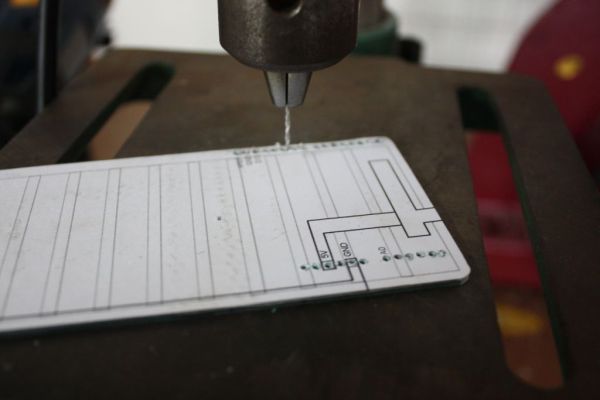
Step 3: Drill the header holes and cut the copper tape
Just drill straight through the paper template to get the header hole placement right.
To cut the copper tape, put it shiny side up, under the tape template, and use a sharp blade to slide out the two tape patterns.
Step 4: Add the copper tape to the backing
The copper tape simply needs to connect the underside of the first solette (this is the (+) of the series arrangement of solettes) with the 5V pin, and then a second piece of tape connects the underside of the last solette (this is the (-) of the series arrangement) with one or two of the GND pins of your power header.
Step 5: Add the Analog and Power Headers
To do this, I snipped the headers down a bit, to make sure the tops did not protrude from the upper surface of my backing. And then I slipped in two blobs of solder on the underside of the backing, at the 5V and GND pins. This turned out to be easier than I expected, as the solder wicks right along the copper tape nicely. I needed to reheat the solder a second time to get the headers properly aligned, but it worked out fine.
Read more: Arduino Solar Shield – A DIY solar source for your projects without waiting for PCBs