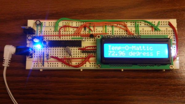
I have loved making projects with Arduinos, but at $30 a piece your projects can get expensive. So I want to show you how you can make your own Arduino from scratch and save money doing it. Make your own Arduino for around $8. For this instructable I show you how to make one on a breadboard and with it make a digital thermometer.
Step 1: Parts you need for the Arduino:
- Full Size Breadboard ($8 adafruit.com)
- 22 AWG Wire or jumper wires ($6 adafruit.com)
- 1 – 7805 Voltage Regulator ($0.18 taydaelectronics.com)
- 2 – LEDs ($0.02 each taydaelectronics.com)
- 2 – 220 Ohm Resistors ($0.10 each taydaelectronics.com)
- 1 – 10k Ohm Resistor ($0.10 taydaelectronics.com)
- 2 – 10 uF Capacitors ($0.01 each taydaelectronics.com)
- 1 – 16 MHz Clock Crystal ($0.07 taydaelectronics.com)
- 2 – 22 pF Capacitors ($0.10 for pack of 10 taydaelectronics.com)
- 1 – Small Momentary Normally Open “off” Button ($0.05 taydaelectronics.com)
- 1 – Breadboard-friendly 2.1mm DC barrel jack and 9V Wall Wort with 2.1mm Plug (2.1mm jack $0.95 adafruit.com)
- 1 – ATMega328 with Bootloader ($6 adafruit.com or cheaper other places if you can add your own bootloader)
Many of these parts you can also buy from Radio Shack.
Assuming you have a breadboard, wire, and a way to program (see step 4) the Arduino parts cost a total of $7.71 +shipping.
Step 2: More Power Captain!
Connecting the power source:
Plug in the 2.1mm barrel jack on the side of the breadboard like in the picture and add jumper wires going across the middle. (instead of the barrel jack and wall wort you can use a wired up 9v battery)
Add the 7805 power regulator and the lines to power the board. It’s input from the external power supply goes in on the left, ground is in the middle and the 5V output is on the right (when facing the front of the regulator). Add power OUT and ground wires that connect to the right and left rails of the breadboard.
Also, add a 10uF capacitor between the IN of the regulator and the ground (between the plug and 7805) as well as a 10uF capacitor on the right rail between power and ground. The silver strip on the capacitor signifies the ground leg.
Add power and ground wires at the bottom of your board connecting each rail. So now the bottom and top have power and ground. (see pic)
Now you are going to add the power “on” indicator. Add an LED and a 220-ohm resistor on the left side of your board behind the barrel plug. An LED attached to power like this is a great troubleshooting trick. You’ll always know when your board is being powered as well as quickly know if your board is being shorted.
Plug in the power to turn it on and see if your LED lights up. If it does you are good to go for the next step. If not, check all the steps and cross reference with the pictures to find any errors.
Time for the “All Mighty Arduino!!!”
Step 3: Brainzzz!
It’s Arduino Time (see pictures for more details)
Take a moment to review the Pin Mapping (picture) of the Atmega. (Atmega168 and 328 have the same pin map.) When “pin” is mentioned it is in reference to the chip’s pin not digital pin or analog pin.
Add the small tactile switch so that you can reset the Arduino whenever you’d like. Add the switch just above the top of the Atmega chip crossing the gap in the breadboard. Then, add a wire from the bottom left leg of the switch to the RESET pin of the Atmega chip and a wire from the top left leg of the switch to ground. Connecting a 10k ohm pullup resistor to +5V from the RESET pin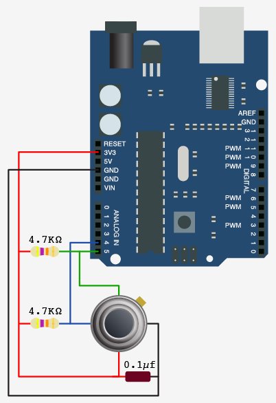
Connect to power(5v) and ground.
Pin 7 – Vcc – 5v
Pin 8 – GND
Pin 22 – GND
Pin 21 – AREF – 5v
Pin 20 – AVcc – 5v
Add a 16 MHz external clock between pin 9 and 10, and add two 22pF capacitors running to ground from each of those pins.
Now your Arduino should be all set, but lets test it. First add an LED just down from the Atmega and run wire from it’s positve side to pin 19. Add a 220ohm resister from the LED’s ground side to the ground rail.
Now let’s make that LED Blink.
Step 4: Programing…
1. If you have another Adruino you can use it to program your chip by carefully swapping out the chip it came with. OR
2. You can buy a “FTDI friend’ from adafruit.com $14.75 That is what I used.
If you aren’t using this go the to next step.
It comes with a 6 pin row. Put this in (see pic) and connect as follows going left to right.
- To ground
- Not used
- To 5v
- To pin 2
- To pin 3
- To pin 1
Now with that connected you can plug in the FTDI friend and program it through USB from a computer with the Arduino software.
(Note: don’t plug in both the FTDI friend and the external power at the same time)
Read more: Arduino from Scratch Digital Thermometer