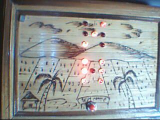
This was a fun project. Push the red button, watch the dice ” ROLL ” then stop on a random roll most every time.
The hart of this game is the ATMEL ATmega328P on a stand alone board. Powered by 4 AA NiMD batteries.
Can you find the SECRET SWITCH in the main picture? Where is the SECRET SWITCH?
The first person that answers the TEST question correctly will win a PRO 3 month subscription to Instructables.
This project was from 2 different places. The schematic from here and the code from there.
The blood and sweat from me.
I am not skilled enough yet to actually write code so Maewert was gracious and offered his code for this project. Also he took time to answer a lot of my coding questions.
Thanks Buddy.
Video Link. to YouTube to see this in action.
 Code.zip8 KB
Step 1: Resources and Materials
Arduino on a Breadboard
http://itp.nyu.edu/physcomp/Tutorials/ArduinoBreadboard
http://itp.nyu.edu/physcomp/Tutorials/ArduinoBreadboard
http://itp.nyu.edu/physcomp/images/tutorials/Arduino-USB-BB-10.jpg
http://www.instructables.com/id/Arduino-eletronic-double-dice/
BOM:
- 1 ATMege328P-PU
- 1 28 Pin Socket
- 1 Perfboard
- 1 16 Mhz Crystal
- 2 22pF Capacitors
- 1 10K ohm Resistor
- 1 Tact Switch
- 1 NO Push Button
- 14 LED’s
- 14 220R Resistors
- 1 Reed Switch
- 1 Small Magnet
- 4 AA NiMD batteries
- 1 Battery Holder for the AA Batteries
- ? Various wires ect
- 1 Project Box
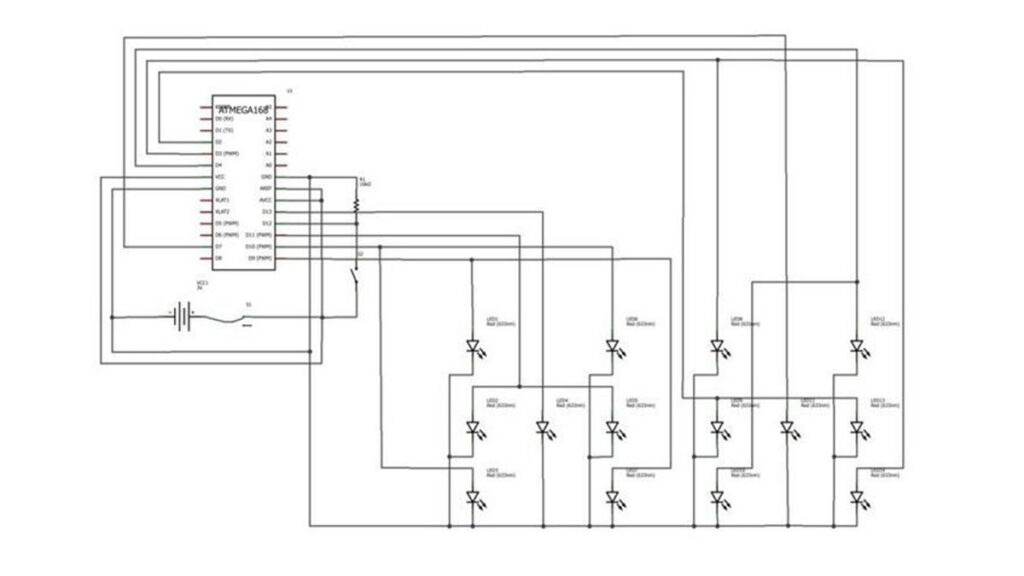
Step 2: Schematic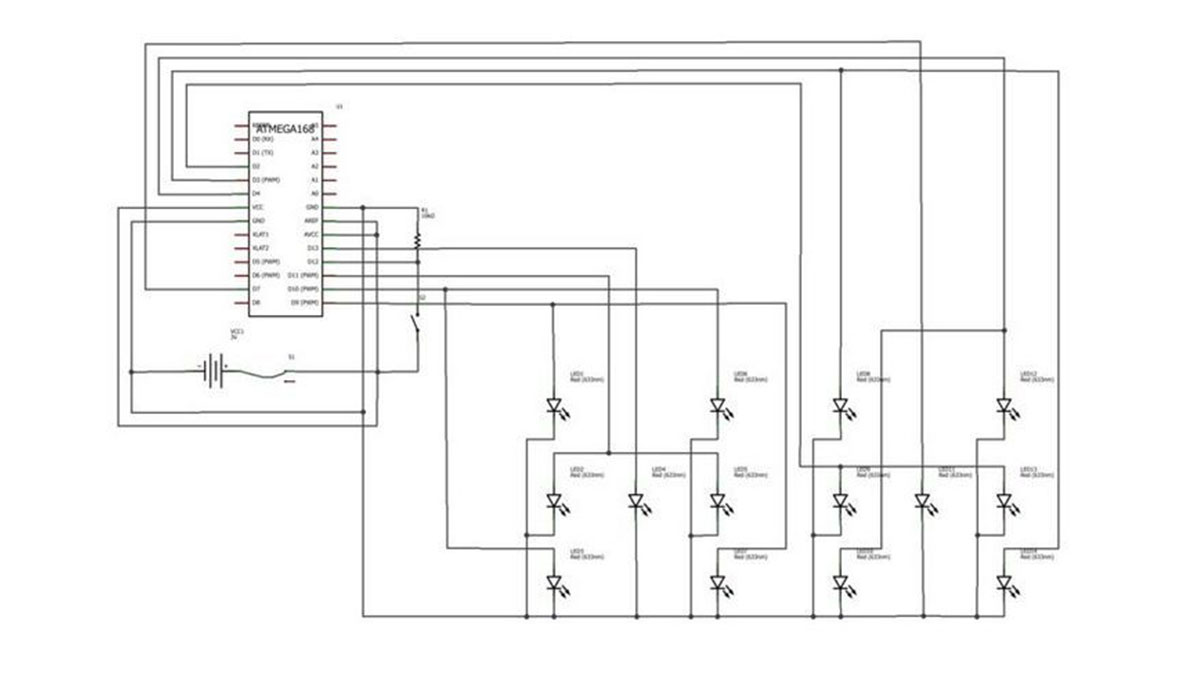
ATmega328P is really over kill for this little project. So i tried to burn a ATtiny2313 with this code using an Arduino as an ISP, not successful.Then i decided to to re burn the 328 bootloader with an 8 Mhz clock so as to use less components in the project. 8 Mhz would be just fine to use, the ATtiny 2313 runs at 8 Mhz anyway. Not successful.
So i am using a 328P at 16Mhz with an external crystal for this project.
FYI a ATmega328 is not supported by Arduino so make sure you get a ATmega328P or ATmega328P-PU.
Step 3: The Box
I have had it for several years so it is a little rough from ware.
Measures 5″ tall. 7 1/2 ” wide. 5 1/2 ” deep.
I believe i paid $1.16 US money.
Step 4: Prepare the Box
Lay the template on you box where you see fit. I put mine direct in the upper center. Left room the the Dice Roll switch at the bottom of the LED’s.
Step 5: The Build, LED’s
I put all the cathodes to the outside so i could bend them flat to each side. Then i cut the cathodes and the 220R resistors very short.
Soldered the resistors from the cathodes to the ” flat wire “. The flat wire is used for making custom Nicd battery packs so it conducts and solders very well. The two center LED’s i had to make the resistors L shaped to fit well to the ground strap.
The LED’s are wired; Bottom Left to Top Right together. Bottom Right to Top Left together. Left Center and Right Center together, then Center is all by itself. That gives 4 connections per dice. The 4 wires per Dice go to the ATmega 328P, plus ground. 9 wires we need to run to the 328P.
Step 6: The Build, Circuit
I used my 28 pin socket on a different project, so i used 2 14 pin sockets. They were a little tight in the center where they came together, so a little sanding was in order to make a comfortable fit.
Blue wire for the upper dice and white for the lower dice.
Red for positive and black for negative.
The 328 was programmed on my Aceduino then transferred to the project board.