Recently, I decided I would like to attempt to make a passcode lock with my newly acquired Arduino Uno, but all the tutorials I could find made use of a modified keypad, something that not every Tom, Dick and Harry has lying about. I therefore decided to set out and make a version using only things every Arduino user should have in their component box – buttons.
Ladies and Gentlemen, I bring to you – the Arduino Combi-button Lock!!
This example will cause only an LED to come on when the passcode is entered, but other features can easily be added, such as a servo, motor etc.
If you do not wish to use buttons, there is an alternative TouchOSC version for Android or iPad/iPhone/iPod touch. Just skip step 4.
This is an entry for the Microcontroller contest. If you think it’s awesome, be sure to vote!
So let’s get started!
Step 1: Components – What you will need
To make this lock, you will need:
Essentials
-> An Arduino board – in my case an Arduino UNO I purchased from oomlout.co.uk. I bought the starter kit, and I would highly recommend it – go check them out!
-> A USB type-A to USB type-B cable
-> The Arduino IDE – download from arduino.cc
-> A breadboard
Hardware version:
-> 4 x push buttons/switches
-> 4 x 10k ohm resistors
iPhone/iPod Touch OSC Controlled version:
-> TouchOSC app ($4.99 on AppStore, and I believe it is free on Android)
-> TouchOSC layout editor
-> The Processing IDE – download from processing.org
Step 2: Preparation – Setting up the breadboard
Plug one of the bus rails along the side into the 5v pin on the Arduino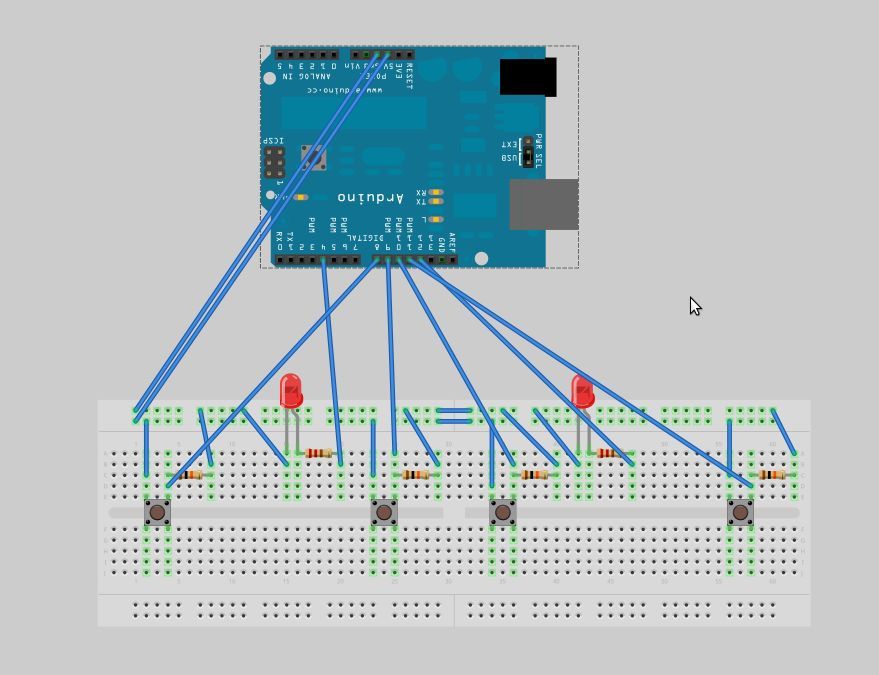
Plug another bus rail into a ground (GND) pin on the Arduino
Step 3: Let there be light! – setting up the LEDs
Plug both the LEDs into the breadboard, longer leg on the left ( to make following this tutorial easier).
Next, plug a 560ohm resistor into the rail connected to the longer leg (+ve) of each LED, and take the red LED’s resistor to Arduino digital pin 4. Then take the other end of the green LED’s resistor to pin 12 on the Arduino.
Finally, take a jumper wire, and join the other leg of the red LED to the GND bus rail, and do the same for the green LED.
Step 4: Physical Version – Buttons
Please Note: It is important that none the buttons are connected to the same rows occupied by the LEDs (two for each or three for each, depending on which setup you chose in the previous step).
Plug a button over the gap in the middle of the breadboard – make sure this goes the right way round. You might have to bend pins.
Next, plug a 10k ohm resistor from one leg of the button to the GND bus rail, and use a jumper wire to connect the other leg on the same side of the gap to the 5V rail.
Read more: Arduino Combi-button Lock optional Android support