So I decided I’m going to make more of my Arduino projects with 3.3Vdc AtMega328s. Now I’ve done this before but will go through some of the problems.
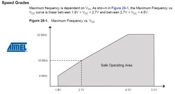
PROBLEM: The standard Arduino uses a 16MHz crystal. Now if you look at the documentation, the AtMega328P will operate from 1.8 to 5.5Vdc. However, the speed grades chart shows that the AtMega328P may not work with a 16MHz crystal at 3.3Vdc. (See chart)
SOLUTION: So the preferred solution is to switch the crystal to 8MHz.
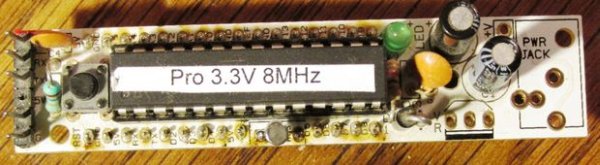
Step 1: Prototype of Arduino 8MHz 3.3V
Well, I have this one setup to use a USB-BUB or in my case a USB-BUB substitute, PL2303. I made these with my USB Arduino Instructable:
http://www.instructables.com/id/Arduino-USB/
These can supply 3.3Vdc.
So my first thought was that the PL2303 IC is supplying the 3.3Vdc and maybe it can’t supply enough current. I haven’t seen how much 3.3V current the IC supplies and it also powers itself.
SOLUTION?: Well, I tried adding a 3.3Vdc regulator powered by 5Vdc to see if that fixed the problem. Still didn’t work. I tried different crystals and different AtMega328 chips, still no luck.
SOLUTION: Well, I remembered my friend OffTheRails2010 saying that the cylindrical quartz crystals (see picture) won’t work on a prototype board, though they work okay when soldered onto a PCB. I did some testing and found that the cylindrical crystals would work but the voltage had to be over 3.45Vdc on my particular setup. Well, the protoboard seems to work okay with a regular 8MHz crystal.
Step 2: Implementation of Arduino 8MHz 3.3V
One really nice Arduino 8MHz 3.3V (no shield) is the Sparkfun Arduino Pro Mini 328 3.3V/8MHz:
https://www.sparkfun.com/products/11114
But for prototyping a good Arduino I like is an RBBB.
http://moderndevice.com/product/rbbb-kit/
So I decided to modify one:
The RBBB kit comes with a 16MHz resonator. (I don’t remember but I think I bought RBBB blank PCBs and not kits). Anyway, I don’t like to use resonators so I used a 16MHz crystal and two 22pF capacitors. For my Arduino 8MHz 3.3V, I used an 8MHz watch crystal and two 22pF caps. The second and third pictures show how I soldered the parts to one of my RBBBs.
The RBBB can be powered by a 7-12V wall wart but as you might be able to tell, I haven’t soldered in a Pwr Jack or regulator. I could actually use a 3.3Vdc regulator but haven’t found the need to yet.
Another way, the RBBB can receive power is with the six pin strip on the left side. The third pin from the bottom is labeled 5V and supplies power to the AtMega328.
Okay, this six pin connector is designed to be used with the USB-BUB (See picture):
http://moderndevice.com/product/usb-bub-i/
This module converts a computer USB signal to the serial signal needed by the AtMega328. It also supplies 5Vdc for the RBBB. Now this is pretty nice as you only have to have one USB-BUB but can use it on many different RBBBs.
ASIDE: The USB-BUB is a fine product and I do have one. But I don’t like spending that much so I found a substitute using the PL2303 for a lot cheaper on ebay and modified them to work with the Arduino:
http://www.instructables.com/id/Arduino-USB/
The USB-BUB and my clone supplies 5Vdc but also has a pin to supply 3.3V. So I modified my RBBB accordingly. First, I unsoldered the 5V pin so that it would be less likely to overpower the PCB. Then on the bottom of the RBBB pcb, I jumpered the 3.3V pin to the 5V pin which supplies power to the AtMega328P (See pictures).
Step 3: Software
SOLUTION: Well, the Arduino environment has a solution. Under Tools, Boards, there is a selection called Arduino Pro Mini (3.3V 8MHz) w/ Atmega328.
HINT: I think this originated when the Sparkfun Pro Mini (3.3V 8MHz) was created. I also believe there are some other selections that may work (Arduino Fio?).
PROBLEM: The standard Arduino bootload will not work with this selection. The bootload on the AtMega328 needs to be changed.
SOLUTION: Some of you may already have a method to do this but here is one fairly simple way to do it:
http://arduino.cc/en/Tutorial/ArduinoISP
Now I have a special ISP cable to do this and I recently converted my MTS_Optiloader PCB to do this but I use the same basic software procedure as above.
When selecting the Atmega328 8MHz bootload, I use:
Arduino Pro or Pro Mini (3.3V, 8 MHz) w/ ATmega328
Once the Atmega328P is bootloaded, I would suggest you label it as 8MHz.
Caution: Being a GEEK, I’m programming a lot of Arduinos, some which are 16MHz and some 8MHz. Try to remember to select the correct ‘board’. I just tried to program an 8MHz with Arduino UNO selected, it failed to program. So it shouldn’t cause major confusion.
Step 4: Increasing 3.3V current
Now most of my prototyping and Arduino PCBs use the PL2303 (USB-BUB) interface so I would like a little more current. Most good personal computers supply 5Vdc at 500mA. All of the PL2303 modules pass the 5Vdc directly through so the 5Vdc will supply 500mA.
So I decided to make an adapter for my PL2303 modules to use a 3.3Vdc voltage regulator connected to the modules 5Vdc. I used an L4931C33 regulator which can supply 300mA of current.
Another problem with this PL2303 module is that the pin order is not the same as the RBBB so I had to make special cables to attach the two. I designed this PCB so that the PL2303 can solder into the PCB and a six pin female header can be soldered coming out so that it will plug right into my RBBB. See pictures.
I’ve included the Eagle Cadsoft files.
TIP: Not all PL2303 modules have this particular pinout so this may not work with all modules.
TIP: I made this using single sided PCB so the six pin header I used had longer pins so that I can solder them on the ‘opposite side’.
Conclusions: So far my RBBB Arduino 3.3V module and my PL2303 3.3V adapter works pretty good.
Step 5: Pro Mini
So I recently bought some Arduino Pro Minis (clones?):
http://www.aliexpress.com/snapshot/6093806779.html
I bought the 5Vdc/16MHz version as they’re a lot cheaper. These are very inexpensive often as cheap as the AtMega328 chip itself. But I wanted to make them into 3.3Vdc versions.
They do sell 3.3Vdc versions but all the ones I’ve seen are more expensive.
HINT: There are at least two versions of these modules, using different versions of the AtMega328 and different types of crystals. The two headers on the top and bottom and the one on the right (see picture) should remain the same.
PROBLEM: The standard Pro Mini uses a 16MHz crystal.
SOLUTION: On my Pro Minis, the 16MHz crystals are standard HC49 crystals and I have some 8MHz versions.
NOTE: Some of the other Pro Minis use a different type of crystal.
PROBLEM: Since we’re changing the crystal, we also need to change the bootload software.
SOLUTION: The same link for changing the software can be used. The AtMega328s are soldered onto the Pro Minis but the same pins are available on the connectors so the bootload can be changed without removing the AtMega328.
Read more: Arduino 3.3V