This project will guide you through the steps to make an Arduino based 360 degree rotating foam ball turret with full joystick wireless control, and first person view camera and headset.
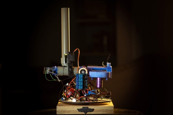 This is a moderately complex project for hobbyists looking to try something a little extra. Parts of this project were limited by component availability and time, so we encourage you to make it your own and modify and improve the design. You can follow step by step, use bits of it, or just the code, to make your own foam ball turret.
This project will involve:
- Basic woodworking
- Basic metal working
- Soldering
- Arduino programming
- 3D printing
- Laser cutting (or patient sawing by hand)
Coding skills you’ll get to try out:
- Wireless communication
- Brushless motor control
- Servo control
Supplies
Links to the specific components we used are attached.
250 x 250mm heavy wood
About 600 x 300mm 6mm plywood
Arduino Uno – £17.00
Arduino Nano or Nano Every – £10.00
7.4V 3800mAh LiPo battery – £35.57
2x Brushless 1980KV motors – £21.70 each
2x ESC motor controllers – £13.41 each
2x 2.4GHz WiFi module + Shield – £2.60 each
Voltage step-up converter – £3.99
5V Arduino Relay – £5.49
47mm O.D Thrust Bearing – £14.03
2x 26mm O.D Axial Bearings – £3.06 each
10mm Aluminium Rod (or similar)
36mm plumbing pipe and Right angled 3 way adapter
Plastic 70mm O.D Wheel set (for Firing) – £4.20
MG996R 360 Degree Servo (for Rotation) – £9.00
MG946R Servo (for Tilt) – £8.00
DS329HV Servo (for Trigger Firing) – £7.89
2x DF5015SM 12V Blower Fan – £2.48 each
FPV Camera – £16.99 (optional)
FPV Headset – £43.99 (optional)
3D Printer
Laser cutter (or hand saw and some patience)
Total Cost: £268.64 (much cheaper if you already have parts lying around)
3D printed parts:
- 360 degree servo mount
- Tilt servo mount
- Launch wheel / motor holder
- Blower fan holder
- Barrel holder
- Servo to shaft mount
- Camera Mount
Step 1: Background: Launching
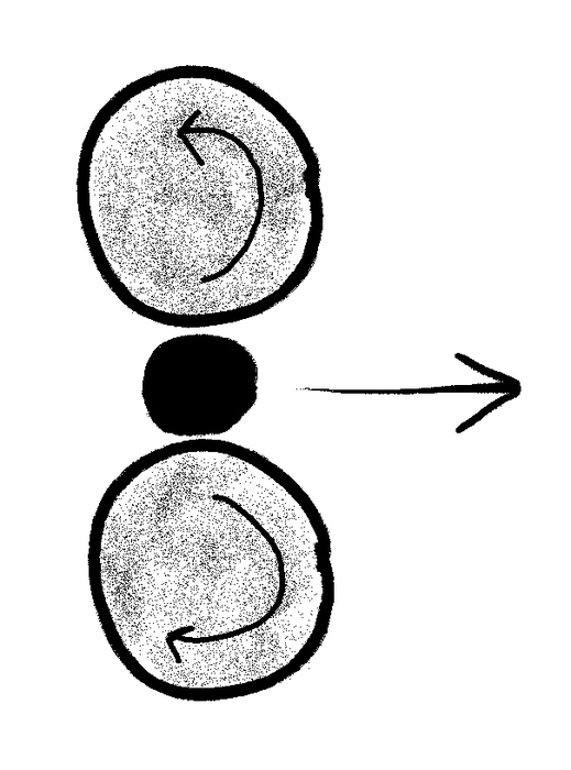 The mechanism this turret uses to fire foam balls is opposing rotating wheels. When a ball is pushed between these wheels it is quickly accelerated and fired out the front. Pay close attention to position the wheels the exact diameter of the size of ball you plan to fire, for us we are using the Nerf foam balls at about 20mm diameter.
Step 2: Background: Loading the Launcher
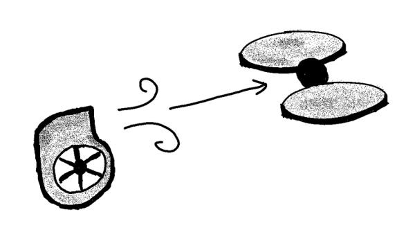 To get balls into the launch wheels, this turret uses blower fans at the far end of the barrel. These produce a wind which is strong enough to blow any foam ball dropped into the barrel along it to the end where the launch wheels fire it. This allows you to drop a ball into the barrel while it is aimed up at an angle of about 30 degree, rolling the ball up hill to the launch wheels.
Step 3: Background: Aiming
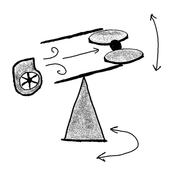 To aim the turret, the whole launch assembly and barrel is mounted on a frame, allowing it to tilt up and down, which is mounted on a turntable, allowing it to turn 360 degrees around.
Step 4: Background: Loading and Triggering
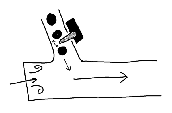 In order to maximise usage, a vertical tube can hold multiple foam balls, which can be dropped into the launch tube by turning this servo arm, acting as the trigger.
Step 5: Assembly: Main Frame
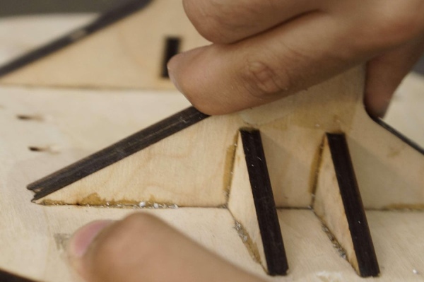 The frame is designed to be laser cut out of 6mm plywood (although you can cut it by hand with a lot of patience)
Some parts needed to be thicker, so double layers were used to make 12mm parts. Slots and tabs were also added to the design for increased strength and to help part alignment. Use wood glue or PVA to secure together the frame.
From the DXF file, you will need:
2x each of the upright pieces to make 12mm thick vertical support arms (2x left and 2x right)
1x of the circular pieces
4x of the triangular braces
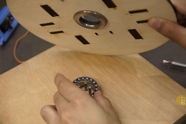
Next, insert the axial bearings into the cut-outs, and secure with epoxy.
Finally, epoxy one half of the bearing to the underside of the turntable, aligning it perfectly to the cut-out.
(Attached at this initial step are all the files you need to laser cut and 3D print)
Attachments
- Turret laser cut 2.1.DXFDownload
- Blower Mount.STLDownloadView in 3D
- Camera Mount.STLDownloadView in 3D
- Motor Holders.STLDownloadView in 3D
- Pipe Mounting Bracket.STLDownloadView in 3D
- Tilt Servo Mount.STLDownloadView in 3D
- 360 Servo Mount.STLDownloadView in 3D
- Eagle Badge.STLDownloadView in 3D
- Pipe Ball Forcer.STLDownloadView in 3D
Step 6: Mechanics: Building the Base
 The turret needs something heavy and sturdy for the turntable to rotate on. We made a 250mm square base from 2 layers of 18mm plywood for a total 36mm depth.
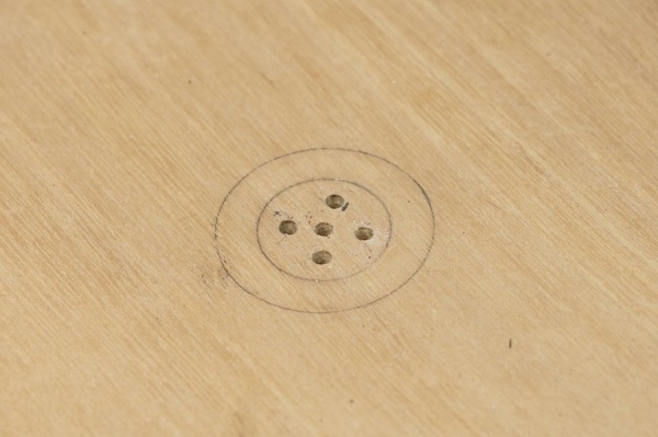
On the top layer, drill out the pattern of five 3.5mm holes as shown, ensuring the outer four holes are within the inner 30mm diameter circle and are not drilled all the way through. This is the outline of the thrust bearing.
On the bottom layer of plywood, drill a large diameter hole, ours is about 30mm. This is so that later on we can secure the servo shaft to the underside of the top layer of this base with a nut and bolt.
Cut 4 short lengths of 3mm aluminium rod, approximately 27mm length. These will engage the servo faceplate later and allow it to turn itself against this base.
Lay one half of the bearing down and the track too. It does not need to be secured.
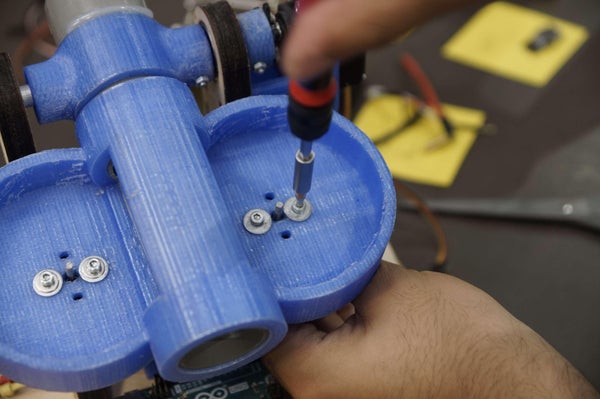
Step 7: Assembly: Turntable Servo
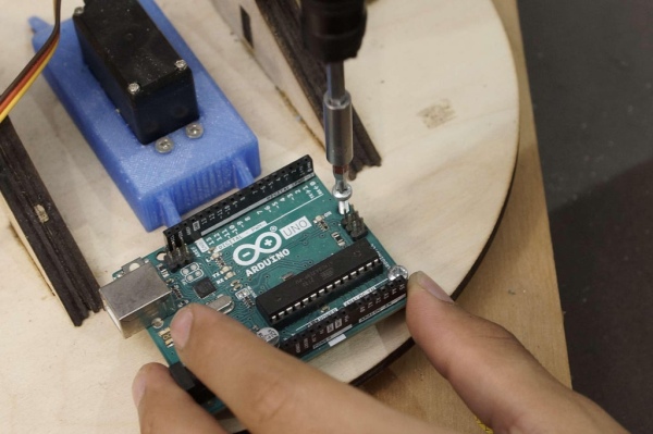 Mount the Arduino to the front of the turntable (side with shortest servo mount legs) using stand offs and M3 bolts. Drill 3.5mm holes for the bolts to go through to secure the stand offs with nuts on the underside.
Step 9: Assembly: Securing the Turntable to the Base
 Mount the Arduino to the front of the turntable (side with shortest servo mount legs) using stand offs and M3 bolts. Drill 3.5mm holes for the bolts to go through to secure the stand offs with nuts on the underside.
Step 9: Assembly: Securing the Turntable to the Base
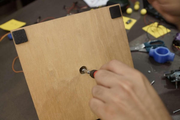
To stop the turntable lifting off, you can screw in a straight thread M3 rod into the servo faceplate. Once screwed into the faceplate, add locking nuts and screw down the rod until they pull the two parts together. Apply enough tension to keep the bearing halves together, but not too much to restrict movement.
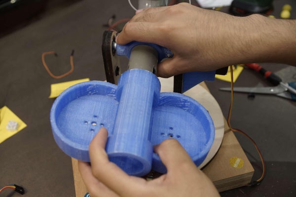
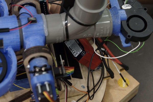
Step 10: Assembly: Launch Barrel
 The barrels and feeder were made from 36mm waste plumbing. Cut a 170mm length part for the barrel and a 250mm length for the feeder.
Also, you will need to cut two slots in the front end of the barrel for the wheels to slot through to fire the foam balls. The slots should start 20mm from the front of the barrel, and be 70mm long, with a height of about 25mm. Have the centre of the slot in line with the centre of the barrel, and symmetrical on the left and right.
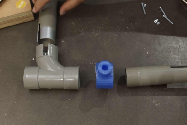
Also, cut a slot in the elbow joint and feeder tube. The barrel should point forwards over the Arduino. Slot together the parts as shown and place them in between the frame vertical arms and note the side of the elbow joint that points towards the grid of six slots in the vertical arms. On the opposite side is where the feed slots need to be cut. Cut a 10mm wide notch, 25mm down into the curved arm of the elbow joint. Insert the feeder tube, and match the cut on the tube.
Assemble the parts again and slide the barrel mount 3D print over the barrel, as shown.
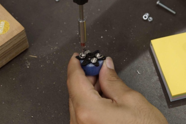
Step 11: Assembly: Barrel Shaft
 Cut a 26mm length of 10mm diameter aluminium rod, and a longer 40mm length. On the 40mm length, drill two 3mm holes through the diameter of the rod 5mm and 8mm from either end. These will be used with M2.5 bolts and nuts to secure the 3D printed mounts to the shaft.
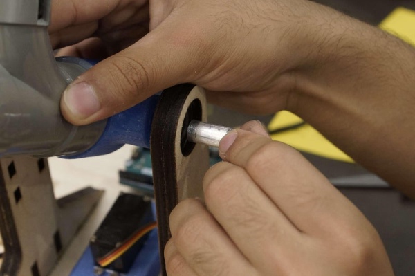
Hold the barrel assembly in place, pointing over the Arduino, and slide in the shorter shaft through the bearing into the 3D printed mount on the side without the grid of six cutouts.
Slide the longer tube into the other side, and mark on the 3D print where the hole in the shaft is. Drill through the 3D print to line up and put a M2.5 bolt through the print and shaft to lock the two together. Use a nut on the other side to secure.
Step 12: Assembly: Tilt Servo
 Screw the servo’s faceplate into the 3D printed adapter ring. At the same time, leave space between the screws to drill through a hole similar to the barrel mount, so that another M2.5 bolt can go through this and the other hole in the aluminium rod, securing the servo to the rod which is secured to the barrel mount.
Push the faceplate back onto the servo shaft, and then insert the servo into the 3D printed mount and secure with nuts and bolts.
Step 13: Assembly: Tilt Servo Mounting
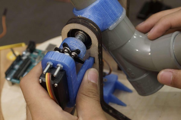 Push the entire servo assembly into the grid of six slots, ensuring the aluminium rod goes into the 3D printed adapter ring and the through holes line up.
Put a M2.5 bolt through the through hole and secure with a nut.
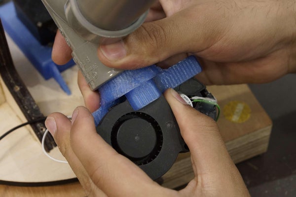
Step 14: Assembly: Blower Fans
 Push the entire servo assembly into the grid of six slots, ensuring the aluminium rod goes into the 3D printed adapter ring and the through holes line up.
Put a M2.5 bolt through the through hole and secure with a nut.
Step 14: Assembly: Blower Fans

Push the blower fans into their 3D printed mount, the back of each fan facing the back of the other, and their outlets lined up on top of each other. You may need to secure in place with epoxy. Push fit this assembly into the rear end of the elbow joint.
Step 15: Assembly: Launch Wheel Motor Mount
 Push fit the 3D printed mount over the barrel, lining up the slots cut in the barrel with the slots in the 3D print.
On the inside roof of the barrel, in line with the slots, stick the alignment piece in place with double sided tape. This is to keep the foam balls in place as they get accelerated between the launch wheels, stopping them jumping over the wheels.
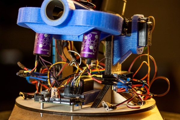
Step 16: Assembly: Brushless Motors
 Screw in the motors using the appropriate sized bolts and a washer. This spreads the pressure over the 3D print. Use as low bolts as possible to give as much clearance between them and the wheels.
Next, mount the wheels. Depending on which wheels you use you may need to mount them differently. Ours uses a tight push fit, strengthened with some epoxy.
WARNING: It’s important to mount the wheels securely. They will be spinning at high speed and may fly off if loose. Only use when it’s safe to do so and wear eye protection when using.
Step 17: Assembly: Camera
 Slide the camera module into the 3D printed module holder, then glue this to the top and front of the launch wheel mount.
Step 18: Assembly: Firing Servo
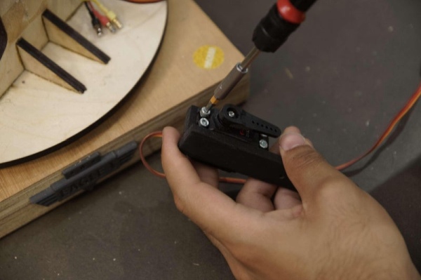 Cut out a small piece of plywood from the off cuts, about 20 x 115 mm. Cut out another two small pieces, about 20 x 10 mm. These will make the mounting bracket for the trigger servo. Holding the servo flat on the long piece of plywood, glue the two pieces in place such that they can be used to screw the servo into using its mounting tabs. We then used zip ties to secure the assembly to the elbow joint through holes drilled in the wood. Simply hold parts in place to determine where holes and zip ties need to be put. The objective is to get the servo arm inside the slot cut out earlier, and at a height where it can turn from pointing straight into the barrel, to pointing straight down, and allowing foam balls to fall through.
Feel free to redesign this as a 3D printed part (we didn’t get the chance to), we’d love to see what you come up with!
Step 19: Assembly: Battery Mount
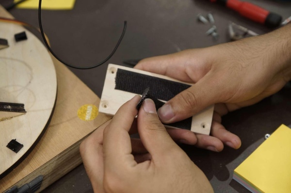 Cut out a 115 x 50 mm piece of plywood and drill 2 mm pilot holes in the corners and countersink. These holes should line up with the two arms of the vertical frame as shown.
Add sticky back velcro to the battery pack and battery mounting plate.
Drill holes pilot holes in the slanted section of the vertical arms to line up wit the battery plate holes, then screw in the battery plate with counter sunk screws so that the battery can lie flush. The battery will not be added yet as it’s good practice to add the battery last.
The main assembly is now complete, next is to wire everything together.
Step 20: Electronics: Overview
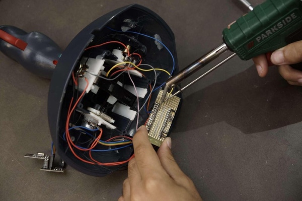
With the main mechanical chassis complete with some of the electronic components in place, it is time to add the rest of them and wire it all together.
The turret is compromised of two main circuits – one for the turret, and another for the joystick – these communicate to each other wirelessly using the nRF24L01 module. With wireless control you gain a lot of freedom with the design since there’s no wires in the way – it makes firing Nerf balls even more enjoyable!
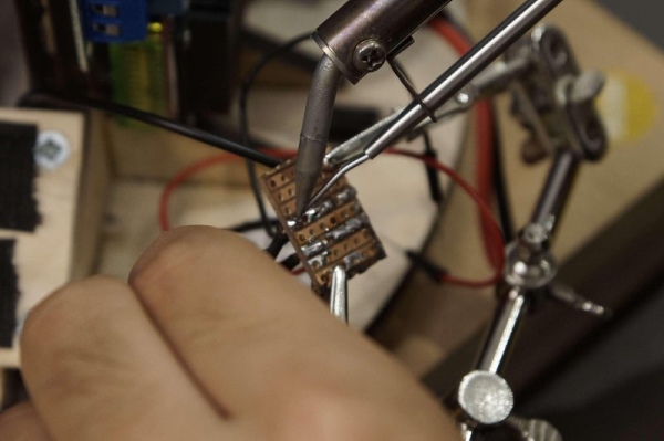
This stage has a lot of flexibility depending on your specific choice of components, but the main key is to follow the circuit diagram. The specifics of how you choose to wire it, cable routing, etc is entirely up to you for what’s convenient. We used jumper cables, electrical tape and terminal blocks to make most of the connections allowing for easy changes and repairs, stripboard for creating power rails and hot glue for fixing components in place.
A main point to note here is the power distribution circuits are really important for delivering the correct voltages and current to the components. Also, programming the ESC to work with the Arduino can be difficult depending on your model, but easy once you’ve found the manual, so hang tight for that.
Please take caution when working with electronics and soldering, using general good practice at all times and ensuring nothing is powered on unless testing.
With that, strap in, it’s time to wire up!
Step 21: Electronics: Turret Circuit Diagram
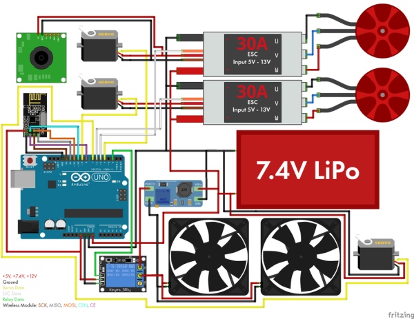 The whole circuit is powered by a 7.4V 3800 mAh LiPo battery pack typically used for RC cars or drones. Be careful when handling LiPo batteries and charging them, reading all safety instructions that came with it.
The 7.4V from the battery is delivered directly to the:
- Arduino
- Continous rotation servo
- Voltage step-up converter
- ESCs
The 7.4V is stepped up to 12V to power the:
- Blower Fans
The 7.4V is stepped down to 5V using the Arduino to power the:
- Relay
- WiFi Module
The 7.4V is steped down to 5V using the ESC Battery Eliminator Circuit (BEC) to power the:
- FPV Camera
- Tilt Servo
- Firing Servo
A BEC is used to remove the need for multiple batteries for the different power requirements of the components. Using the ESCs to power the servos and camera is really useful as it can handle a much higher current output (2A) compared to using the Arduino which can only handle a maximum of around 0.5A.
Since this project is intended for users with intermediate experience, and the components can be adapted, the circuit diagram should be fairly straightforward. If there’s anything you’re unsure about or that isn’t clear, please feel free to leave a comment or message.
Step 22: Electronics: Voltage Step-up Converter
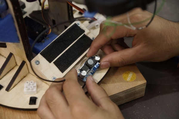 Begin by sticking down the voltage step up converter in front of the battery mount using hot-melt glue. Make sure to position it with enough space to remove the battery when required.
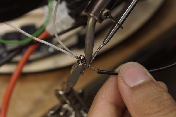
Solder the Input/Output wires on to the board, if you have not already done so. Try to do this before sticking it down.
Connect the Step-up converter to the 7.4V battery connectors and adjust the small potentiometer on top until the output voltage matches the blower fans requirement (12V).
Step 23: Electronics: NRF24L01 Wireless Module
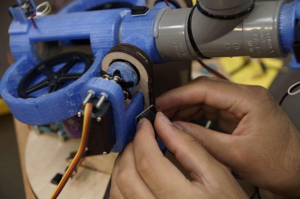 Hot glue the wireless module to the tilt servo bracket. We utilised the module with an adapter board – this includes a voltage regulator to allow it to be powered by the Arduino 5V output.
The pins on the nRF24L01 connect to the Arduino as follows:
- 5V to Arduino 5V
- GND to Arduino GND
- CE to Arduino D8
- CSN to Arduino D10
- SCK to Arduino D13
- MISO to Arduino D12
- MOSI to Arduino D11
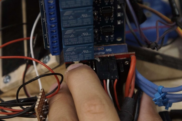
Step 24: Electronics: Relay
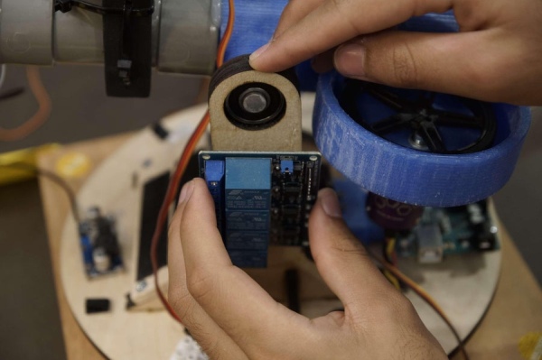 Hot glue the relay to the side of the turret. This will be what switches the blower fans on/off. The relay is great as it is an added layer of safety since the fans can now be turned on and off, but also makes the turret sound more exciting since it makes an audible click when activated.
The pins on the relay connect as follows:
- The +12V wire goes from the blower fan to K4 on the relay. This then comes out and connects to the +IN of the voltage step-up converter.
- 5V to Arduino 5V
- GND to Arduino GND
- IN4 to Arduino D2
Step 25: Electronics: Arduino 5V Breakout Board
 You’ll notice that the Arduino only has 1 x 5V pin, but we are powering 2 components from it (Wireless Module and Relay).
To connect more components we made a small breakout board from stripboard which simply slots into the 5V and GND slots on the Arduino, allowing you to add more components.
Be careful adding anything extra as the Arduno has a max current draw of around 500mA, we’re only using it to power the low current components.
Step 26: Electronics: Blower Fan
 Splice the positive and negative wires for the blower fans so that they are wired in parallel, this way they can be wired into the relay. This will result in the voltage requirement staying the same at 12V, but the current draw doubling from 0.18A to 0.36A.
Solder the -VE directly to the voltage step-up converter.
The +VE wire will be connected in line to the relay next.
Step 27: Electronics: ESC and Brushless Motors
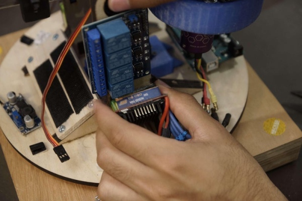 Hot glue the ESC on to the side of the turret.
Add a terminal block connector to the side to connect the power wires of the ESC to the battery.
Wire up the 3 Brushless Motor connections to the ESC. The order does not matter, but can be swapped if you need to change the direction of the motor.
Connect extension wires to the BEC (+5V and ground) on the ESC. These connections will later be used to connect the servos.
The signal pin on the ESC labelled (RECIEVER S) goes to the Arduino. This is D6 Arduino for ESC 1 and D5 Arduino for ESC 2. This can be wired directly or using a seperate stripboard (we did the latter as it was easier to troubleshoot).
Connect the switch that came with the ESC to the SW pins. This will vary depending on your specific ESC.
Repeat for the ESC on the left side of the turret and the right side of the turret.
Note: On the left side, the BEC of the ESC powers the tilt servo and the camera. The ESC mounted on the right side of the turret only powers the firing servo.
Step 28: Electronics: Tilt Servo and Firing Servo
 To make connections to the ESC easier, we created another breakout board (this is optional as wires can be connected directly instead).
This breakout board has the +5V from the BEC on the ESC. It then leaves the data pin of the servo free to connect to the Arduino data pin. For the Tilt Servo this is D9, for the Firing Servo this is D7.
This needs to be repeated for both ESCs for each servo respectively.
In summary, power 1 servo from 1 ESC, connect the data pin of the respective servo to the Arduino.
Step 29: Electronics: Battery Power
 Create a stripboard piece for distributing the power from the battery to the various components. In this case, the stripboard piece has the +7.4V from the battery and ground, which then connects to the continous rotation servo, the Arduino and the voltage step-up converter.
This stripboard is then connected to a terminal block. You will notice that we used black for all the wiring here as that’s all we had lying around (not a good idea for seeing where things are connected so avoid it if you can). Use thicker gauge wire here as these connections will have the most current going through them. You will notice that going into the battery terminal block are 3 sets of wires – this is the stripboard connection (for components mentioned previously), left ESC and right ESC.
Connect the Battery Wires (not connected to battery yet) to the terminal block.
Connect the 7.4V wire to the Vin pin on the Arduino and Battery Ground to Arduino Ground.
That should complete the power distribution for the turret.
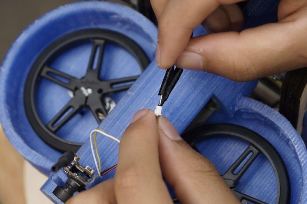
Step 30: Electronics: Continous Rotation Servo
 Connect the data pin of the continous rotation servo to D4 on the Arduino.
Connect the power to the 7.4V battery power distribution board made earlier.
Step 31: Electronics: Checking Arduino Connections
 Check that all your power and data connections match the circuit diagram and provided code.
Labelling your wires or colour coding them can help in identifying or troubleshooting later on. We wanted to use parts that we had lying around, hence the not so organised colour scheme (promise we’ll improve it in v2).
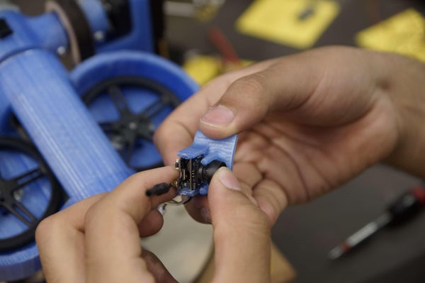
Step 32: Electronics: FPV Camera
 Connect the power wires from the ESC to the power connector of the FPV camera.
The camera being used can take between 2.9 – 5.5V, so is suitable to power using the ESC BEC.
Use a cable clip to neaten any loose wires.
Insulate any exposed connection with electrical tape or heatshrink.
Step 33: Electronics: Joystick Circuit Diagram
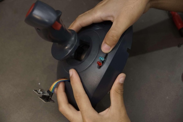
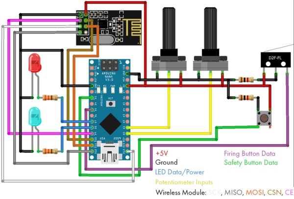 The second circuit is for the joystick control. This is USB powered and uses an Arduino Nano. A lot of the work here is just rewiring an existing controller (the simpler the controller is, the better) and making sure it all works.
We chose to use a vintage Logitech Wingman (Model 3001) as it simply uses 2 buttons and 3 potentiometers, perfect for hacking! Going with this really makes the experience feel special as the joystick is really well moulded, however feel free to 3D print your own or choose a different joystick.
The main parts of the circuit are:
- nRF24L01 for wireless control connected to D9, D10, D11, D12, D13
- 2 Potentiometers wired to A0 and A1 for analog control
- 2 buttons wired to D3 and D5 for safety and firing
- 2 LEDs for state indication (wireless connection and safety light showing blower fans on) connected to D7 and D8
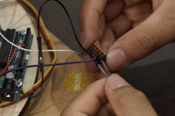
Step 34: Electronics: Rewiring Joystick Potentiometers
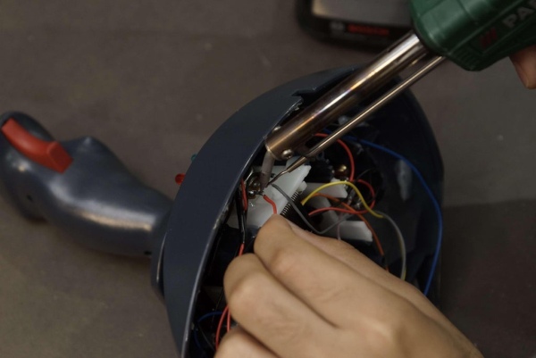 Check all the connections of the potentiometers – these should already be in the controller. Connect the grounds and +5V wires to the Arduino, then to the respective analog pin.
Be wary! If you have an old controller, the potentiometers may not work reliably so you might have to swap them out with new ones. We spent a lot of time troubleshooting code, only to realise that the original hardware wasn’t working properly. Save yourself the time and just wire a new one if it doesn’t give consistent values.
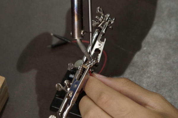
Step 35: Electronics: Rewiring Joystick Buttons
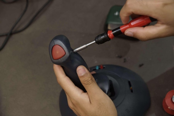 Check all the connections of the buttons – these should already be in the controller. Connect the grounds and +5V wires to the Arduino, then to the respective digital pin.
You may need to add a pull down resistor to ensure it registers correctly on the Arduino. We used a 1K resistor on the ground pin for each button.
Track the wires down the shaft and keep track of the colours so you can wire them correctly to the Arduino.
Step 36: Electronics: Joystick NRF24L01 Module
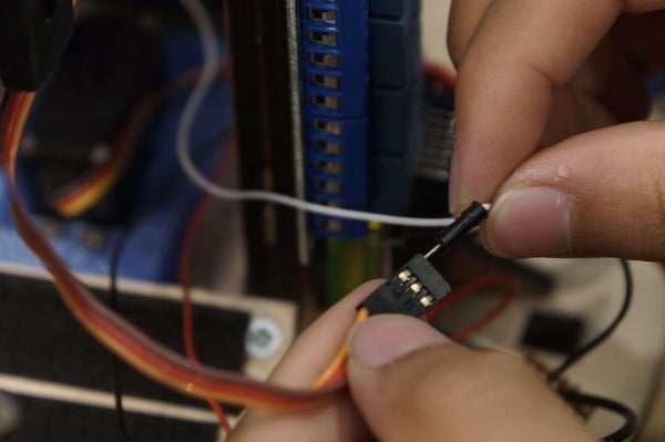
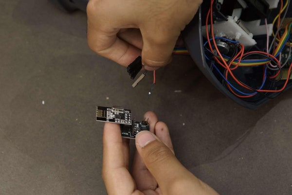 Feed the wires into the controller for the wireless module. We utilised the module with an adapter board – this includes a voltage regulator to allow it to be powered by the Arduino Nano 5V output. We didn’t want to glue anything to the controller body so left the module hanging – this should be fine as there’s no physical force being applied to it.
The pins on the nRF24L01 connect to the Arduino as follows:
- 5V to 5V Arduino
- GND to GND Arduino
- CE to Arduino D9
- CSN to Arduino D10
- SCK to Arduino D13
- MISO to Arduino D12
- MOSI to Arduino D11
Step 37: Electronics: Joystick Indication LEDs
 Route 2 LEDs through the Joystick. These will be used to indicate if both Arduino’s have successfully connected with each other (Blue). The second LED (Red) will illuminate when the safety is turned off and the turret is ‘live’. The safety makes the firing button inactive and the blower fans remain switched off.
Step 38: Electronics: Arduino Nano Joystick
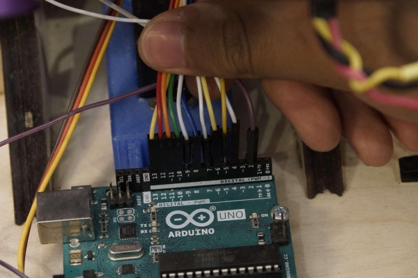
 Wire up the Arduino Uno to all the components as shown in the circuit diagram. We used stripboard to mount the Arduino in place. We then used a drill to seperate the connections on the stripboard since they would otherwise be on the same rail.
Tie a knot in the USB cable for strain relief and hot glue it into place. Connect it to the Arduino Nano and route the cable out of the controller. Finally attach the metal plate back on the bottom, then we’re ready to test.
Step 39: Electronics: Testing the Controller
 Test the pitch of the controller (for controlling the tilt servo), the roll (for controlling the continous rotation servo) and buttons (safety and firing). Use serial monitor on Arduino IDE to see what values register and if everything is working correctly.
The joystick should now be complete!
Step 40: Code: Overview
This instructables is already very long, so we’ll keep this section brief.
The challenge of this project is constructing the turret and wiring it all up. If you’ve done it according to the instructions, then hopefully the code should be good to go. It has been commented in detail meaning it should be easy to adapt if required. I highly recommend you read through this as a lot of time was spent commenting the code.
There are 2 .ino as there are 2 Arduinos to program.
All the libraries required are listed at the top of the code. It uses the SPI.h, nRF24L01.h and Servo.h libraries.
Step 41: Code: Arduino Uno
A few brief points to note on the Uno code.
The ESC is controlled using PWM through the ‘Servo.h’ library.
The address for communicating to the Arduino Nano is set as ‘RxAAA’ and is established as a read-only variable. This can be changed, or in the future can be secured through encryption.
The data is transferred as a single array which contains 4 values – servo tilt angle, servo rotation direction, firing state and ESC speed. This is then delivered to the Arduino Nano which reads the array and uses each value for the respective function. This is a highly efficient and robust way to transfer data compared to sending 4 seperate values, making the turret respond rapidly without delay. A snippet is shown below.
//a single array that holds 4 values which will be read from the incoming Nano signal
//This is more efficient and robust than trying to send 4 seperate values, instead a single message is recieved
int message[4];

//each variable name is self-identifying to the turret
angle_val = message[0];
rotation_val = message[1];
escSpeed = message[2];
firing_state = message[3];
The Uno receives radio transmission. We use the lowest data transfer rate of 250kbps to get the highest range possible. The nRF24L01 has 6 pipes that it can use to transmit or receive data to at a time. In the setup part of the code, we open the pipe and set it as listening, since the Uno will be recieving all the commands from the Arduino Nano.
//this starts radio transmission and utilises the RF24 module<br>radio.begin();
//the lowest data transfer rate provides greater connection range
//since a single array is being received, this rate is suitable as the more important factor is the wireless range
radio.setDataRate( RF24_250KBPS );
//the nRF24L01 has 6 pipes that it can transmit or receive data to at a time
//this command opens the first data pipe for reading at the address we defined earlier
radio.openReadingPipe(0, address);
//Since the UNO is only receiving data, it must start listening for any values coming through the aforementioned ReadingPipe
radio.startListening();
The general way the code works is that it’s listening to messages from the Arduino Nano. Then it will write whatever the last value it receives and set the pin to that value. For the contionous rotation servo, we had to tune the point at which the direction changes as this will vary servo to servo. In the neutral position, to ensure the servo does not move, we use the detach command to disengage it.
For the firing servo, on the Uno side of the code, it’s simply checking if the firing state is on or off, and if the ESC speed exceeds a threshold (in this case if it’s rotating), then sends a signal to the servo so that it either blocks the balls or feeds the balls in.
The speed of the brushless motors is set by the ESC, which takes in commands written in microseconds from the Arduino. The data is continously sent to the ESC, even when stationary they are set to be idle, so that it always knows its throttle position. Interfacing an ESC with an Arduino can initially be challenging depending on the model, but straightfoward once you have the ESC manual.
In summary, download the .ino file and read the comments, there’s a lot more detail.
Attachments
Step 42: Code: Arduino Nano
The Nano code works very similarly to the Uno code except instead of listening to commands, the Nano is only sending data out as a transmitter. Once again, my recommendation is to read the comments in the code as it’s been done with a high level of detail.
The main points here are to tune the potentiometers depending on how you’ve fixed them into the joystick so that they correspond with the values that are sent to the servos. The main function used here is map, where the analog reading of the potentiometer is taken (in this case it reads between 390 and 600), then it remaps these to servo values (105 to 160). A snippet is shown below:
////////////////TURRET TILT POT READING//////////////////<br>  //reading the potentiometer values from the analog pin, this is between 0 and 1023
  angle_val = analogRead(angle_pot);
  //since the potentiometer is mechanically fixed in the joystick, it only travels between 390 and 600
  //in order to write a suitable value to the servo, the potentiometer value is mapped accordingly
  //this keeps all the functionality of the potentiometer code within the Nano making reprogramming and adapting of the input controls later easier
  angle_val = map(angle_val, 390, 600, 105, 160);
The ESC continously has a 1500 microsecond signal passed to it. ESCs are typically used when you have a remote control with a throttle, and upon startup you set the min value and max value, then let the throttle spring back to neutral position. By setting the 1500 microsecond signal, we are essentially providing a neutral position. We are not however changing the throttle incrementally to min and max at startup, and need to reprogram the ESC settings so that it works with the Arduino – we will walk you through the basis of this in the next step.
The last part of the code defines the 4 values to send to the Arduino Uno into a single array message as mentioned earlier and then sent using:
//'sizeof' is a command for writing the message to the address, the second argument confirms the number of bytes occupied in the array and how many should be received
//using '&' in this instance will pass the address of the variable where the data is stored
  radio.write(&message, sizeof(message));
Just like before, download the .ino file and read the comments, there’s a lot more detail.
Attachments
Step 43: Code: Arduino ESC Settings
 Attached are images from the manual demonstrating how to set throttle range. The run mode needs to be switched to ‘ONE’ to allow for simple control of the ESC through an Arduino.
Use the button on the side of the ESC to reprogram it to the correct mode, then it should be ready to use with the Arduino.
Upon startup you’ll hear a set of beeps (this is the Arduino setting the idle speed), then a startup jingle which indicates the ESC is calibrated and ready to use.
The full manual has been attached for the ESCs used in case it is of interest. If you are using a different ESC then please refer to its respective manual.
Step 44: Final Setup: Connecting the FPV Headset to Camera
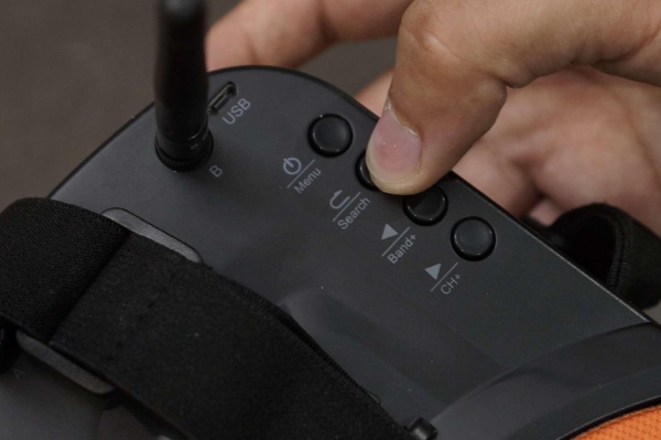 What’s better than firing your wireless Nerf sentry gun? Being able to fire it in a different room and as if you’re sat at the end of the barrel.
It is an optional feature and will help reduce the cost of the project, but if you do include it, it makes the experience a lot more epic.
Once you’ve wired your camera in and charged the headset. It’s as simple as hitting search and waiting for the headset to find the same channel that the camera is on. You may have to manually set the channel if it does not work, referring to the user manual of the headset you chose. If it still doesn’t work then either you need to charge the headset more, or if it was a cheap one, then you need to get it replaced (we did).
Word of warning. Using the headset for too long can cause nausea, especially if you’re spinning the turret around a lot. So please be careful.
Step 45: Testing: Power It Up!
 Finally, mount the battery in place and connect the negative and positive terminals.
The ESC should beep a couple times and make the calibration tune (this is the Arduino setting the throttle values as mentioned in the coding section). This should take a couple of seconds.
Your wireless Nerf shooting sentry gun is ready to use!
For a more immersive experience, use the headset for FPV.
Please remember to never aim at people and use with caution. Although this is fun to play with, it is not a toy and can be dangerous if misued, so please remember to be safe.
Happy Turreting!
Step 46: Future Developments
We are currently planning on making a v2 of this turret and are very open to any suggestions, improvements or new designs. Please leave any thoughts in the comments below!
Read more: Arduino NERF Ball Wireless FPV Sentry Turret