In contrast to devices controlled from a web browser or phone, these are designed to be simple, Arduino based devices that are capable of talking to each other bi-directionally. They may be in the same house or in different buildings and may have one way communication (e.g. a light switch and light) or two way (e.g. an automation controller).
It’s possible to have local Device/Relay combinations to control Mains socket power to TVs, Computers etc..
Also you could see this working in building control. Commercial examples that work over local or proprietary interfaces are : Clipsal C-Bus, X10, Bus-SCS.
The Picture shows an example of what we’re trying to achieve using the commercial C-Bus devices as an example.
(http://en.wikipedia.org/wiki/File:CBus_Wiring.gif). But in our case the C-Bus is replaced by the Internet or a Local Network.
Practically speaking, it would make most sense to have one device per room with several switches, sensors and possibly low-voltage motors wired into it, and one device at the distribution board controlling relays or dimmers.
A major factor in Energy Waste is having Lights on too brightly during periods when a room is adequately lit from Natural Light. Adding a Light Sensor Device in a Room with a Dimmable Light Device significantly increases Energy Efficiency by controlling the Room Light in response to the sensed light in the room.
==========
By the way. If you like this Instructable, you might also like:
Digital Thermometer for your Home:
http://www.instructables.com/id/An-Arduino-Thermometer-with-Digital-Display/
Internet-Radio:
http://www.instructables.com/id/Arduino-Raspberry-Pi-Internet-Radio/
Make your own “Wii-Remote” like control of a PC Flight Simulator
http://www.instructables.com/id/Flight-Simulator-with-Arduino-and-Python/
==========
Step 1: You Will Need
* An Arduino (Uno)
* An Ethernet shield (or Wifi)
To prototype:
* A breadboard
* Some LEDs, Wires and Switches
For Mains Control:
* A Mains Relay Arduino Shield (e.g. http://www.dfrobot.com/index.php?route=product/product&product_id=496)
We won’t be covering the Mains Control because it’s covered in lots of tutorials and there are a lot of shields available.
Step 2: Prototyping the Arduino Internet Device
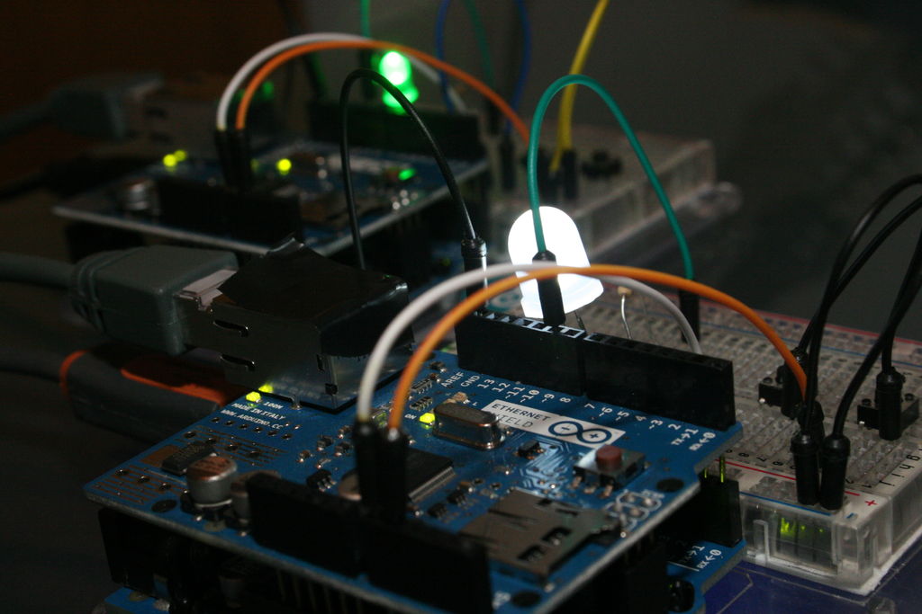
To do that we’ll be prototyping it with LEDs and Switches. Once the Arduinos are talking and controlling LEDs, making it work with Mains Relay shields and motor shields is straight forward.
We’re going to construct a device with switches and LEDs, and we’ll connect 2 of them over Ethernet. That way we’ll be protoyping both the Switch function and the Light Control function at the same time and demonstrating bi-directional comm’s.
For many Devices we should connect them via a Router. If we only have 2 devices (as we do here) then we can connect them to each other. The Ethernet IC takes care of the required Crossover.
We need to give some thought to how one device knows the address of the device it wants to communicate with.
Here’s how we’ll approach it:
Each Device has its own static-IP address. Each Device “knows” which device it wants to talk to. Therefore we can hard-code the Static-IP address of the destination device in the Arduino Code of the Transmitting Device. Not the most elegant solution. But completely practical.
Step 3: Connect the Circuit
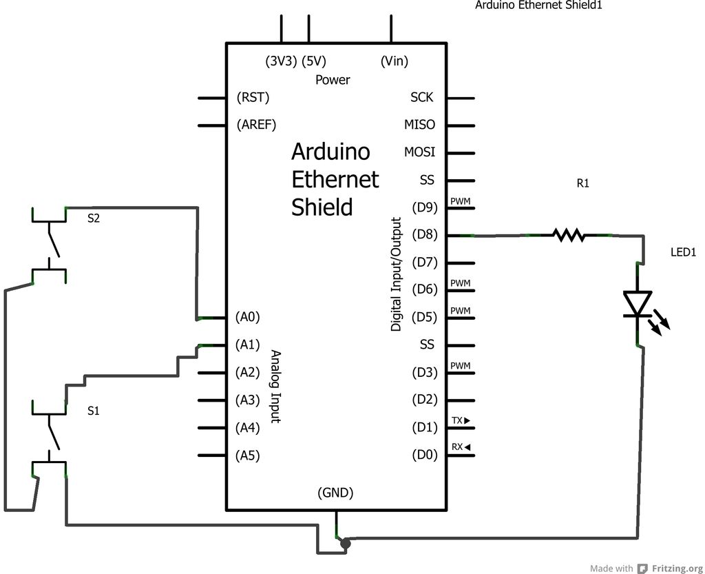 Build an example Device as shown in the diagrams. In fact, build two of them. We’ll need one to talk to the other.
Each Device consists of:
1. An Arduino (Uno)
2. An Ethernet Shield
3. An LED and Resistor to represent an Output Light.
4. Two Switches to represent an ON/OFF Switch panel or UP/DN Dimmer (for example).
Once you’ve built them plug both into your PC USB for programming.
Plug an Ethernet cable from Device 1 to Device 2 (the crossover is taken care of in the Ethernet Shield).
Step 4: UDP Communication
We’re going to use UDP for communication over the Internet.
UDP is an Internet Protocol (so is TCP). So our communications will be UDP/IP.
http://en.wikipedia.org/wiki/User_Datagram_Protocol
To Send a UDP packet we use the Arduino Ethernet library as follows:
1.
First we have to define our IP address and the address of the receiving device, as well as the Ports we’re sending and receiving on:
byte mac[] = {
0x90, 0xA2, 0xDA, 0x00, 0x85, 0x46 };
IPAddress ip(192, 168, 2, 177);
IPAddress rem_ip(192, 168, 2, 178);
unsigned int localPort = 8887; // local port to listen on
unsigned int remPort = 8888; // remote port to send to
2.
We start up the Ethernet and then UDP services (remember it’s UDP over Ethernet -UDP/IP)
Ethernet.begin(mac,ip);
Udp.begin(localPort);
3.
When we want to send a message it needs a start, beginning and end:
Udp.beginPacket(rem_ip, remPort);
Udp.write(snd);
Udp.endPacket();
4.
For Receiving we look for a non-zero packet size being received:
int packetSize = Udp.parsePacket();
and read it into the rcv buffer:
Udp.read(&rcv,size);
Read more: Internet Devices for Home Automation