
n this tutorial we are going to show you how to setup your own temperature and humidity sensor.
We are going to use a DHT22 unit, which is a low-cost digital output relative humidity and temperature sensor. The device includes a capacative humidity sensor and a thermistor to measure air temperature
DHT22 Specifications
- Temperature Range: -40 – 125 ˚C (± 0.5 ˚C)
- Humidity Range: 0 – 100% (2.5%)
- Sampling Rate: 0.5 Hz Operating
- Voltage: 3 – 5V
NOTE: A slightly cheaper option than the DHT22 is the DHT11. Its specifications aren’t quite as good with a temperature range of 0 – 50˚C and 20 – 80% humidity range – but it might be suitable for what you need.
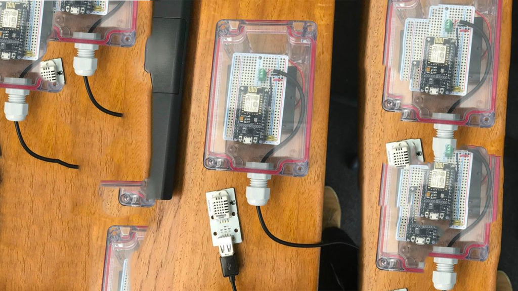
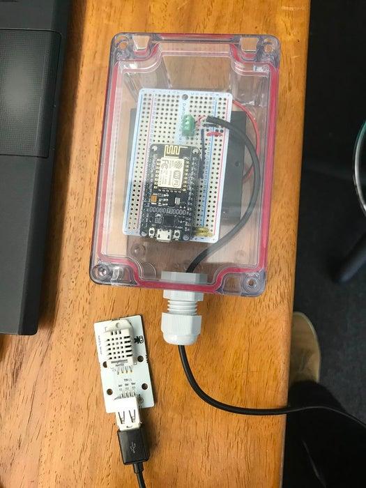
Step 1: Components
- NodeMCU
- DHT22 Sensor
- 10K Ohm Resistor
- LED
- 220 Ohm Resistor
- Push Button
- Bread Board. (We’ve used Adafruit Perma-Proto BreadBoards)
- Enclosure and cable gland
- 4x AA Battery holder & Batteries
Step 2: Wiring It Up
 Here is the basic wiring diagram for the device. You can see what the final version looks like at the end of this instructable.
Whilst not needed we’ve included the push button in order to publish a manual reading.
Step 3: Source Code
For our weather sensor we are going to be posting data to the readiness.io service. For that we’ve created a readiness.io library which takes care of the wifi and service connections. We’ve also split out all the configuration variable in to a separate .h file.
You can download the full source code here
weatherSensor.ino
#include”DHT.h”
#include
#include
#include”config.h”
constint LED_PIN = 0; // The pin connecting the LED (D3)
const byte INTERRUPT_PIN = 12; // The pin connect the test button (D6)
volatile byte interrupt = 0;
#defineDHTPIN4// The Digital Pin the sensor is connected too (D2)
#defineDHTTYPE DHT22 // Designated the type of DHT Sensor
DHT dht(DHTPIN, DHTTYPE);
readiness_io client(CHANNEL_ID, TOPIC, SENSOR_ID, VERSION, FORMAT);
Ticker timer;
voidsetup() {
pinMode(LED_PIN, OUTPUT);
pinMode(BUILTIN_LED, OUTPUT);
digitalWrite(BUILTIN_LED, HIGH);
pinMode(INTERRUPT_PIN, INPUT_PULLUP);
Serial.begin(115200);
Serial.setTimeout(2000);
while(!Serial) { } // Wait for serial to initialize.
Serial.println(“Device Started”);
Serial.print(“Connecting to “);
Serial.println(WIFI_SSID);
client.wifiConnection(WIFI_SSID, WIFI_PASS);
attachInterrupt(digitalPinToInterrupt(INTERRUPT_PIN), buttonInterrupt, FALLING);
timer.attach(UPDATE_RATE, writeToServer);
client.testConnection();
}
voidbuttonInterrupt() {
interrupt++;
}
/* Interrupt timer for sending data to the Readiness.io server */
voidwriteToServer(){
interrupt++;
}
voidloop() {
if(interrupt>0){
/* Read from the DHT22 Sensor */
float h = dht.readHumidity();
float t = dht.readTemperature();
/* Write data to a json string and send to the server. */
String weather = “\”humidity\”:” + String(h) + “,”;
weather += “\”temperature\”:” + String(t) ;
/* Publish data to the readiness_io network */
client.publishCustom(weather);
/* Reset the interrupt variable until the timer interrupt or push button sets it off */
interrupt=0;
}
}
view rawweatherSensor.ino hosted with  by GitHub
config.h
const String CHANNEL_ID = “XXXXXXXXXXXX”; // The Readiness.io channel ID
const String SENSOR_ID = “XXXXXXXXXXXXX”; // Your AgriWebb or made up sensor ID
const String TOPIC = “XXXXXXX”; // The type of sensor or name of the data your sending
const String VERSION = “1”;
const String FORMAT = “”; // leave this blank unless there is a specific readiness format you need.
// i.e. agriwebb
constchar* WIFI_SSID = “XXXXXXX”; // Your WiFi SSID / name
constchar* WIFI_PASS = “XXXXXXX”; // Your WiFi password
constuint16_t UPDATE_RATE = 30; // How long to wait between sending data back (in seconds)
constuint8_t TIMEZONE_OFFSET = 10; // The timezone the sensor is located in (eg. 10 for GMT)
view rawconfig.h hosted with by GitHub
Step 4: The Finished Product
Read more: NodeMCU Humidity/Temperature Unit