
This server room environmental monitoring system is a low cost high performance device with the same onboard features as commercial devices costing hundreds of dollars more. In addition to a low cost platform we will provide low cost sensors for many important devices to insure your equipment stays safe and sound.
Full instructions are available at sproutboard.com as well as several kits to create some very unique projects.
Step 1: Stuff you will need…
You will need a few parts for this build as follows:
Sprout Board: sproutboard.com
Arduino Duemilanove: Trossen Robotics
Ethernet shield: Sparkfun.com
Rack Mount Chassis: sproutboard.com
LCD Screen: Sparkfun.com
Audio Board: Sparkfun.com
Temperature / Humidity Board: sproutboard.com
Power Supply: Sparkfun.com
Odds and ends, screws, glue, tools, etc…
Step 2: Putting it togeather
Step 1:
The assembly of the sprout board is very simple and requires very little experience with soldering. There are a few places where adding components can get cramped, but if you take your time it will be very easy.
Step 2:
Mount your arduino, ethernet shield and lcd screen
Step 3:
Glue the chassis togeather
Step 4:
Mount the board on the chassis
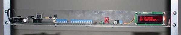
Step 3: Add accessories
Next plug in any sensors you want to. I am using a temp/humidity and sound sensors.
Step 4: Load Software and do a happy dance!
So all we need to do is load our software and do a Happy Dance!
Use this link so anyone can download the pde that will test the system. This also is an excellent framework to customize your application.
Step 5: How to Use It
Pin Assignments
Analog I/O:
Analog 0 – CCD Light Sensor (CDS1)
Analog 1 – Accessory Terminal Block 1 (TA1)
Analog 2 – Accessory Terminal Block 2 (TA2)
Analog 3 – Onboard Accessories Socket 1 (Temperature sensor on external board J9)
Analog 4 – Onboard Accessories Socket 1 (Humidity sensor on external board J9)
Analog 5 – Onboard Accessories Socket 2 (Sound J10)
Digital I/O:
Digital 0 – Not used
Digital 1 – Serial Terminal (TS1)
Digital 2 – Onboard Switch (SW1)
Digital 3 – Onboard Peizo Speaker (SP1)
Digital 4 – LED 1 (LED 1)
Digital 5 – LED 2 (LED 2)
Digital 6 – Accessory Terminal Block 1 (DA1)
Digital 7 – Accessory Terminal Block 2 (DA2)
Digital 8 – Accessory Terminal Block 3 (DA3)
Digital 9 – Accessory Terminal Block 4 (DA4)
Digital 10 – Reserved For Additional Shield (Ethernet shield pins correspond)
Digital 11 – Reserved For Additional Shield (Ethernet shield pins correspond)
Digital 12 – Reserved For Additional Shield (Ethernet shield pins correspond)
Digital 13 – Reserved For Additional Shield (Ethernet shield pins correspond)