Ever wanted an LED tree? Well now you can have your LED tree and eat it too (no, wait, you probably shouldn’t)..
Step 1: Gather the parts
You will need:
1x ATtiny85
10x male header pins
Solid core wire, 2 colors
A bunch of LEDs
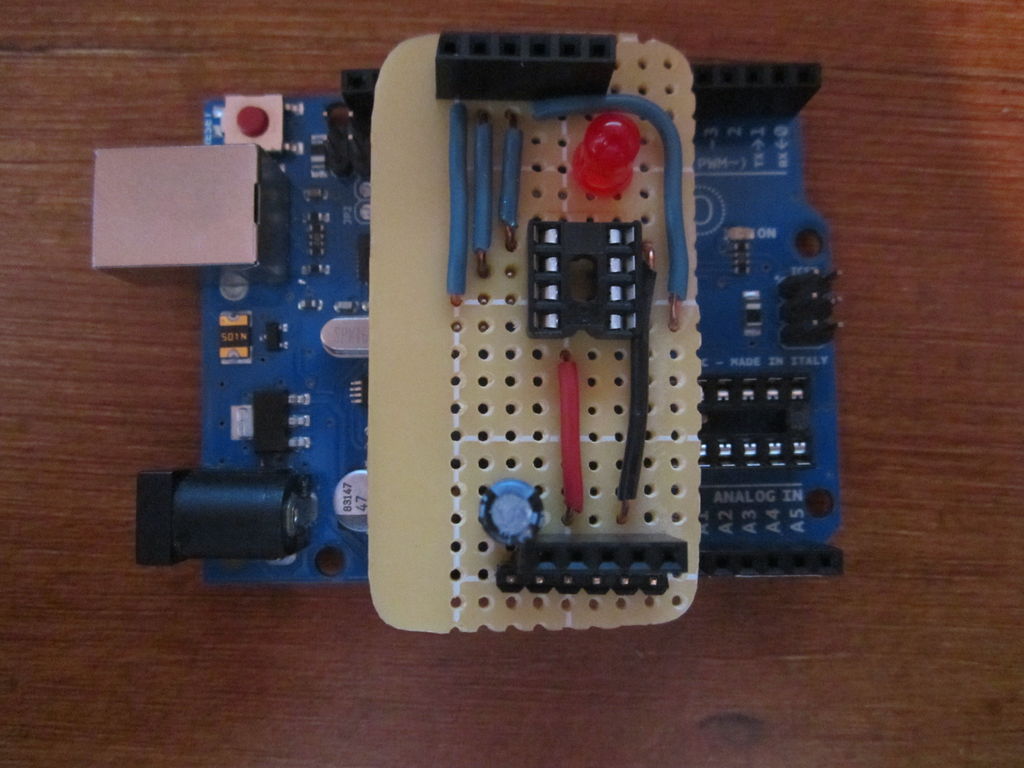
1x Arduino Uno to program the ATtiny
Step 2: Program the ATtiny
To prep the Arduino for programming the ATtiny, follow the guide on this page.
After you have done that, upload this sketch to the ATtiny.

//CODE STARTS HERE
//ATtiny85 RGB color fading tree
const int 2Pin = 2;
const int 1Pin = 1;
const int 0Pin = 0;
void setup()
{
pinMode(2Pin, OUTPUT);
pinMode(1Pin, OUTPUT);
pinMode(0Pin, OUTPUT);
}
void loop() {
2to21();
21to1();
1to10();
10to0();
0to02();
02to2();
}
void 2to21()
{
digitalWrite(redPin, HIGH);
digitalWrite(bluPin, LOW);
// fade up green
for(byte i=1; i<100; i++) {
byte on = i;
byte off = 100-on;
for( byte a=0; a<100; a++ ) {
digitalWrite(grnPin, HIGH);
delayMicroseconds(on);
digitalWrite(grnPin, LOW);
delayMicroseconds(off);
}
}
}
void 21to1()
{
digitalWrite(grnPin, HIGH);
digitalWrite(bluPin, LOW);
// fade down red
for(byte i=1; i<100; i++) {
byte on = 100-i;
byte off = i;
for( byte a=0; a<100; a++ ) {
digitalWrite(redPin, HIGH);
delayMicroseconds(on);
digitalWrite(redPin, LOW);
delayMicroseconds(off);
}
}
}
void 1to10()
{
digitalWrite(grnPin, HIGH);
digitalWrite(redPin, LOW);
// fade up blue
for(byte i=1; i<100; i++) {
byte on = i;
byte off = 100-on;
for( byte a=0; a<100; a++ ) {
digitalWrite(bluPin, HIGH);
delayMicroseconds(on);
digitalWrite(bluPin, LOW);
delayMicroseconds(off);
}
}
}
void 10to0()
{
digitalWrite(bluPin, HIGH);
digitalWrite(redPin, LOW);
// fade down green
for(byte i=1; i<100; i++) {
byte on = 100-i;
byte off = i;
for( byte a=0; a<100; a++ ) {
digitalWrite(grnPin, HIGH);
delayMicroseconds(on);
digitalWrite(grnPin, LOW);
delayMicroseconds(off);
}
}
}
void 0to02()
{
digitalWrite(bluPin, HIGH);
digitalWrite(grnPin, LOW);
// fade up red
for(byte i=1; i<100; i++) {
byte on = i;
byte off = 100-on;
for( byte a=0; a<100; a++ ) {
digitalWrite(redPin, HIGH);
delayMicroseconds(on);
digitalWrite(redPin, LOW);
delayMicroseconds(off);
}
}
}
void 02to2()
{
digitalWrite(redPin, HIGH);
digitalWrite(grnPin, LOW);
// fade down blue
for(byte i=1; i<100; i++) {
byte on = 100-i;
byte off = i;
for( byte a=0; a<100; a++ ) {
digitalWrite(bluPin, HIGH);
delayMicroseconds(on);
digitalWrite(bluPin, LOW);
delayMicroseconds(off);
}
}
}
//CODE ENDS HERE
Step 3: Construct the Tree
First, start by taking two different colors of wire and cutting them into pieces (I cut them about 6 inches long). Then strip the ends off all the wires.
Solder an LED to the end of two different colors of wire (for example, I used black wire for the cathode and green wire for the anode). Then, separate the LEDs with wires attached into 3 groups.
Solder all the anodes of one group together, and all the cathodes of all the groups together, so you have 3 different groups all with a common cathode. I soldered header pins to the end of these groups so that I could easily plug it into a breadboard.