In this article, we are going to interface a Pulse Sensor with Arduino. The pulse sensor we are going to use is a plug and play heart rate sensor. This sensor is quite easy to use and operate. Place your finger on top of the sensor and it will sense the heartbeat by measuring the change in light from the expansion of capillary blood vessels.
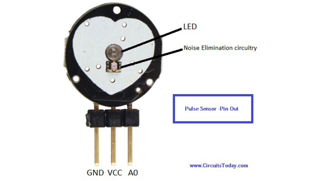
Pin Out – Pulse Sensor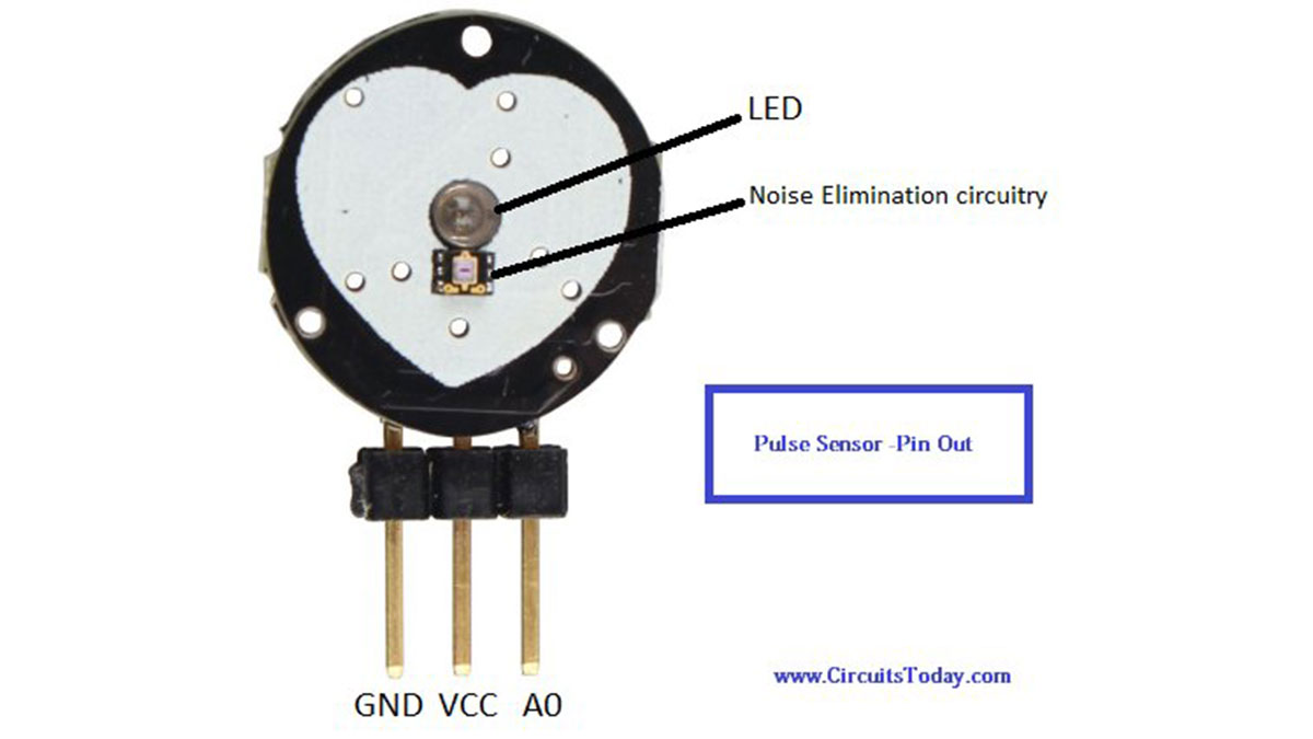
The pulse sensor has three pins which are as described below:
- GND: Ground Pin
- VCC: 5V or 3V Pin
- A0: Analog Pin
There is also a LED in the center of this sensor module which helps in detecting the heartbeat. Below the LED, there is a noise elimination circuitry which is supposed to keep away the noise from affecting the readings.
Working – Pulse Sensor
When a heartbeat occurs blood is pumped through the human body and gets squeezed into the capillary tissues. The volume of these capillary tissues increases as a result of the heartbeat. But in between the heartbeats (the time between two consecutive heartbeats,) this volume inside capillary tissues decreases. This change in volume between the heartbeats affects the amount of light that will transmit through these tissues. This change is very small but we can measure it with the help of Arduino.
Read more: Pulse Sensor and Arduino – Interfacing