Arduino Simple Project for Student
A clear homework list is essential to keep things simple and keep everything tidy. Start with the master list and then divide it into individual lists for each family member. That way, all the work is evenly distributed, and no one has to work inappropriately to maintain the appearance of the home.
Step 1: Hardware Required
Step 2: Board Wiring of Household Task Management
Step 3: Code for Household Task Management (Household Chore)
Advantages of Household Chore Management System
- Working also helps children feel that they are part of the team.
- Children who want to learn responsibility and have important life skills.
- Learn how to manage a home as usual.
- Assign work to other family members, we can work together.
- List of tasks that need to be done on each daily bases.
Household Chore Management System Steps:
Step 1: Hardware Required
- Arduino UNO/Nano
- ISO14443 RFID reader
- Real-Time Clock (RTC)
- 16 x 2 LCD display – This system is used to provide the user interface
- Wago connectors
- Rotary Encoder
Step 2: Board Wiring of Household Task Management
Both the 16×2 LCD display and the DS1307 RTC use the I2C interface, which is easier because it makes wiring much easier, with only one of the wires going to Ardino’s A4 (SDA) and A5 (SCL) pins. Pair is essential.
The MFRC-522 RFID reader uses an SPI interface, which uses fixed hardware pins 11 (MOSI), 12 (MISO), and 13 (SCK). It also requires a slave select and reset line, which I assign to pins 10 and 9 respectively.
Pairing is required for rotary encoder. For maximum performance, this is better if these pins can handle external interference, so use digital pins 2 and 3, currently being used in code, you’ll find it useful to add extra features.
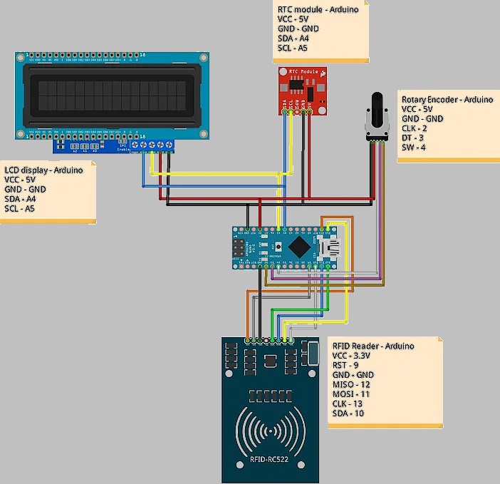
Using WAGO 222-series connector blocks. These are snapshot connectors that provide a robust, easy way to connect anywhere between wires 2 and 8, and are very handy for Arduino projects with multiple modules for sharing in one ground or 5V line. That we need. Required, or say I2C or SPI bus, where you have multiple devices.
Step 3: Code for Household Task Management (Household Chore)
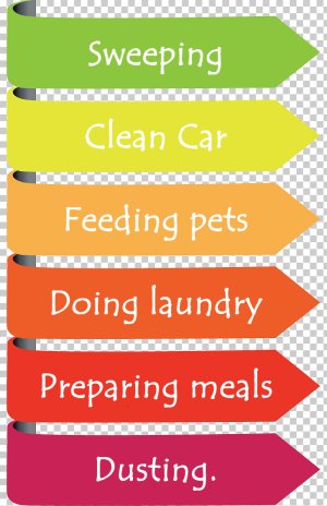
Tasks include a name, which means they will be LCD displays, the frequency with which they need to be performed, and when and by whom. I didn’t save the STL files after printing, but there are plenty of similar. Alternatively, you could construct a nice wooden box, or just use an old cardboard box or Tupperware container to house the electronics.
The central data structure is called the “Task List”, which is an array of tasks. You enter a value of 0 here, the last time you completed, and -1 for the ID of the user that last performed them.
task taskList[numTasks] = {

  { "Sweeping", 7, 0, -1 },

  { "Clean car", 7, 0, -1 },

  { "Feeding Pets", 7, 0, -1 },

  { "Doing laundry", 3, 0, -1 },

  { "Preparing meals", 1, 0, -1 },

  { "Susting", 7, 0, -1 },

};
At the top of the code section, there is a byte value called “ePromSignature”. This value is used to determine whether the data stored in EEPROM is valid. You should increase this value if you ask by changing the structure of the task list item, adding or removing tasks, or adding extra fields. You can think of this as a basic version number system for stats.
const byte eepromSignature = 1;
Initially, the program will only attempt to load the data stored in EEPROM if it matches the data signature entered in the code.
void restoreFromEEPROM() {
   int checkByte = EEPROM.read(0);
   if(checkByte == eepromSignature) {
      EEPROM.get(1, taskList);
   }
}
The LCD display and RTC module use the I2C interface to communicate with Arduino. For this, each device must have a unique I2C address. I’ve tried some different 16×2 display boards, and some use 0x27 addresses, while others use the same board 0x3f. If you find that you do not show only a series of squares and do not enter text, try changing the address value specified in the code.
The LCD display and RTC module use the I2C interface to communicate with Arduino. For this, each device must have a unique I2C address. I’ve tried some different 16×2 display boards, and some use 0x27 addresses, while others use the same board 0x3f. If you find that you do not show only a series of squares and do not enter text, try changing the address value specified in the code.
LiquidCrystal_PCF8574 lcd(0x27);
When an RFID tag is detected, the code reads a 4 byte identifier, and uses it to try to find the user corresponding to the user’s table. If the tag is not recognized, a 4 byte identifier serial monitor will be sent to the console:
int GetUserFromRFIDTag(byte RFID[]){
  for(int i=0; i    if(memcmp(userList[i].rfidUID, RFID, sizeof userList[i].rfidUID) == 0) {
      return userList[i].userID;
    }
  }

Serial.print(F("Unknown RFID card detected: "));
  for(byte i=0; i<4; i++) {
    Serial.print(RFID[i]<0x10 ? " 0" : " ");
    Serial.print(RFID[i], HEX);
  }
  return -1;
}
To assign a tag to a user, you should copy the ID shown and enter the value of 4 bytes in the Users row at the top of the code, along with the corresponding user.
const user userList[numUsers] = {
  { 1, "Ginny", {0x00, 0x00, 0x00, 0x00}},
  { 2, "Harry", {0x12, 0x34, 0x56, 0x78}},
  { 3, "Ron", {0xE8, 0x06, 0xC2, 0x49}},
  { 4, "Hermione", {0x12, 0x34, 0x56, 0x78}},
  { 5, "Alastair", {0x12, 0x34, 0x56, 0x78}},
};