
Currently, we are chasing an invisible monster named Corona Virus ( COVID-19 ) and we are going through the biggest health crisis in our time due to a sharp increase in infection cases. One of the main symptoms of the COVID-19 infected person is an increase in body temperature, in addition to other symptoms such as pain in the body, difficulty in breathing.
It is very essential to monitor continuously the body temperature to detect a corona patient at a very early stage so that proper medication may be taken for fast recovery.
The normal IR thermometer can measure the temperature of a covid patient and also may spread the virus. The main drawback of the handheld thermometer is its performance depends on the operator and the distance to the forehead. To address these problems, a device is made that can be mounted on the wall for fever screening in public areas without an operator. The hardware can measure human body temperature automatically when the distance between the sensor and forehead is adequate.
? My Instagram link: https://www.instagram.com/opengreenenergy/
? My website link : www.opengreenenergy.com
Video Tutorial:
Credit :
The main source of inspiration for this project is from the project iThermowall, I will give full credit to the authors of this project.
I thought this project is very useful in this critical time and I can use my skill to write a DIY guide by including precise instruction and good pictures for illustration so that anyone can recreate it easily.
Supplies
Components Required
1. Arduino Nano ( Amazon )
2. GY-906 Temperature Sensor ( Amazon )
3. OLED Display ( Amazon )
4. Infrared Proximity Sensor ( Amazon )
5. TP4056 Charger Module ( Amazon )
6. 18650 Battery ( Banggood )
7. 18650 Battery Holder ( Amazon )
8. 5 V DC-DC Step-Up Converter ( Amazon )
9. Rocker Switch -15 × 21 mm ( Amazon)
10. 5 mm Green LED ( Amazon )
11. 5 mm RED LED ( Amazon )
12. Jumper Wires ( Amazon )
Tools Used:
1. Soldering Iron ( Amazon / Banggood )
2. Wire Cutter ( Amazon / Banggood )
3. Wire Stripper ( Amazon / Banggood )
4. 3D Printer ( Amazon / Banggood )
Step 1: How It Works ?
 The working principle is very simple, the infrared thermometer sensor MLX90614 reads the human body temperature when the distance ( measured by IR sensor ) between the forehead and the sensor matches a set value. The sensor reading is sent to Arduino for processing and the processed value is displayed on a 0.96″ OLED Display.
Apart from OLED display, two LED and one buzzer is used to indicate the output.
1. When the body temperature is normal, Green LED ( LED1 ) will turn on and the buzzer will beep.
2. When the body temperature is higher than 104 degF, Red LED ( LED2 ) will be ON and the buzzer will beep for a longer time.
Step 2: Power Supply
 The power required for the entire circuit is provided by two 18650 batteries. The two batteries are connected in parallel for making a higher capacity battery pack to get a longer backup. The battery pack is charged by a TP4056 charger module.
The battery pack voltage is stepped up to 7V by using a boost converter module ( MT3608 ). Then the out from the boost converter is connected to Arduino’s Vin pin.
A rocker switch is placed in between the charger module TP4056 output and the boost converter.
Step 3: Prepare the Arduino and Temperature Sensor Board
 To keep costs down, the manufacturer often sends you the board and headers pin but expects you to solder them to the board. I have received the Arduino Nano and MLX 90614 sensor without soldering the header pins.
To solder pin headers to a board, first put the pin headers in a breadboard. That’s optional, but it’s a great way to make sure the pin headers will be perpendicular to the board and parallel to each other, making it easy to insert the board elsewhere. Place the board on top of the headers with the pins going through the holes in the board.
Use a soldering iron with a fine tip since you’ll be working with small parts that are close together. The soldering result should be a cone-shaped bit of solder covering both the circular pad and the bottom part of the pin. There should not be any solder connecting two pins together.
Step 4: MLX90614 Infrared Temperature Sensor
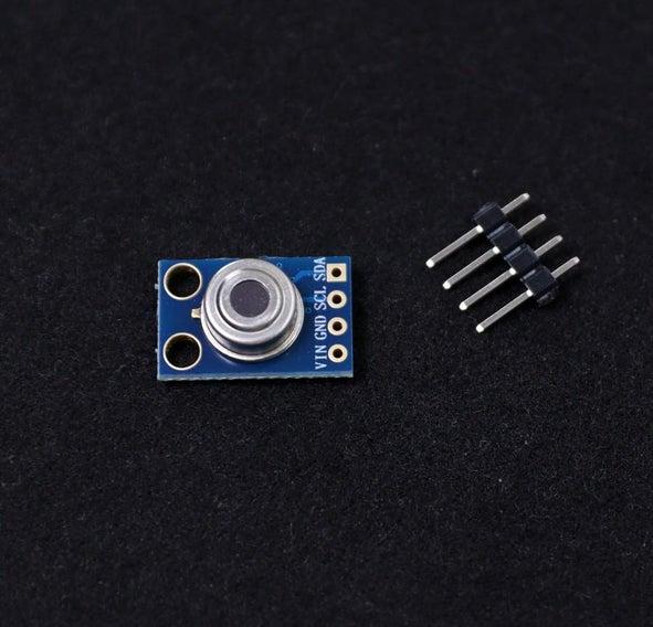 The MLX90614 is an infrared thermometer for non-contact temperature measurements capable of measuring temperatures between -70 to 380°C. The sensor uses IR sensitive thermopile detector chip and the signal conditioning ASIC integrated into a single chip. It works based on Stefan-Boltzmann’s law which states that all objects emit IR energy and the intensity of this energy will be directly proportional to the temperature of that object. The sensing unit in the sensor measures how much IR energy is emitted by a targeted object and the computational unit converts it into temperature value using a 17-bit in-built ADC and outputs the data through an I2C communication protocol.
The sensor measures both the object temperature and ambient temperature to calibrate the object temperature value. The MLX 90614 sensor can read the ambient temperature in the range of -40 to 125 ˚C (-40 to 257 °F) and object temperature in the range of -70 to 380 ˚C (-94 to 716 °F).
The connection of the infrared thermometer with Arduino is very simple since it uses the I2C communication interface like many other components.
The MLX90614 thermometer has 4 pins: VIN, GND, SCL, and SDA.
The connections should be as follows:
Arduino –> MLX 90614
5V —> VIN
GND –> GND
A5 —-> SCL
A4 —-> SDA
Step 5: Prepare the Battery Pack
 We have to connect the two 18650 batteries in parallel. The battery slot that I have used is a two slot holder with independent terminal for connection. To make the parallel connection, connect two terminals on each side together by using a piece of wire.
First apply small amount of flux to the terminals, then short them by using the wire.
Next solder red extension wire to the positive terminal and black wire to the negative terminal of the battery holder.
Step 6: Infrared Proximity Sensor
 Currently, handheld thermometers are quite popular for screening the fever. However, the handheld thermometer performance depends on the operator and the distance to the forehead. To overcome these problems, an Infrared proximity sensor is used to measure the distance between the sensor and the forehead, when the distance is adequate, the temperature reading will be sensed and displayed. In this way, the accuracy of the measurement is improved.
You can set the detection distance from proximity sensor to object by adjusting the potentiometer on the sensor module. Rotating the potentiometer clockwise will increase detection distance and counter-clockwise will reduce the detection distance. I have set this distance to approximately 50 mm.
The connections should be as follows:
Arduino –> IR Sensor
3.3V —> VCC
GND –> GND
D9 —-> OUT
Step 7: OLED Display
 To display the body temperature, a 0.96″ OLED display is used. It has 128×64 resolution and uses an I2C bus to communicate with the Arduino. Two pins SCL (A5), SDA (A4) in Arduino Nanno are used for communication.
I am using the Adafruit_SSD1306 library to display the parameters.
First, you have to download the Adafruit_SSD1306. Then install it.
The connections should be as follows:
Arduino –> OLED
5V —>VCC
GND –>GND
A4—-> SDA
A5—-> SCL
Step 8: LED Indication
 Two LEDs are used to indicate whether the body temperature is normal or abnormal. The green LED indicate when the body temperature is normal and RED LED indicates the abnormal condition ( when the temperature is above 104 degF)
The green LED ( LED1 ) is connected to Arduino digital pin D3 and Red LED ( LED2 ) is connected to D5. To limit the current of the led, two 330 Ω resistors are used. Solder the resistor to the positive terminal of LEDs. The longer leg of the LED indicates the positive terminal.
Connect 4 jumper wires to the LEDs as shown above. Here I have to use female-female jumper wires for easier connection.
Step 9: Buzzer for Alert
 To provide alerts during the screening of the human body, a piezo buzzer is used. The buzzer has two terminals, the longer one is positive and the shorter leg is negative. The sticker on the new buzzer has also ” + ” marked to indicate the positive terminal.
You can solder wires to the Buzzer pins or you may use female jumper wires as I have used here.
The connections should be as follows:
Arduino –> Buzzer
D7 –> Positive terminal
GND –> Negative terminal
Step 10: Prepare an Extension Board
 Most of the modules and components are connected to Arduino pin 5V and GND. Unfortunately, the Arduino Nano has only one 5V pin and two GND pins, but in reality, we need more such pins for connecting the components. To overcome this challenge, I have prepared an extension board by using a small piece of the prototype board.
Apart from the 5V and GND pins we need two SDA and SCL pins for connecting the MLX 90614 sensor and OLED display.
Here I have use right angle and straight male header pins. You can easily make it by following the above picture. In each row, all the pins are shorted.
Step 11: Make the Circuit
Make the circuit by following the schematic diagram given in the above picture. I have already explained the connection details of each component and module. To make it simpler, I have prepared a breadboard circuit for you.
Read more: DIY Non Contact IR Thermometer V1.0