
Hello everybody hope you’re doing well,
in this instructable I’m going to show you how to make a wireless motion alarm system, this device consists of a transmitter and a receiver. So essentially it is a pretty simple and basic wireless motion alarm system with light indication.
Besides being fairly useful it is also a simple project that is great for folks that are just starting to tinker with electronics and microcontrollers because in its concept it is pretty basic and is made from parts that are not hard to find. I will also share with you some tips and tricks on how to do some troubleshooting if you decide to give this project a go yourself.
Supplies
Arduino nano boards 2x
433 MHz transmitter and receiver module
PIR sensor
Switches 2x
LED
100-ohm resistor
Some kind of a box (one for a receiver, and one for a transmitter)
9v battery connector 2x
Tools Soldering iron as well as some solder, utility knife, pliers, wire cutters, drill.
Step 1: Get Your Components
 In the photos above you can see the main components required for this project.
Step 2: PIR (passive Infrared) Sensor
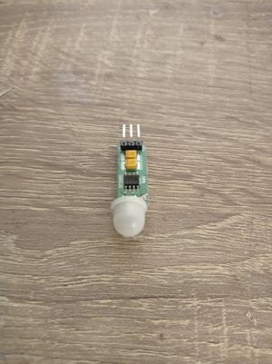 A passive infrared sensor (PIR sensor) works on the principle that it measures infrared light radiating from objects in its range, these kinds of modules are small, low-power, easy to use, inexpensive and they are reliable. Because of those reasons, they are commonly used in security alarms. They are also easy to communicate with microcontrollers, which makes this type of sensor ideal for this project.
PIR sensor used in this project has 3 pins:
positive voltage-VCC,
ground-negative supply,
output,
in this step solder 3 wires, one wire goes to the VCC pin, the other one goes to ground (-), and the third one goes to output.
Step 3: 433 MHz RF Transmitter and Receiver Module
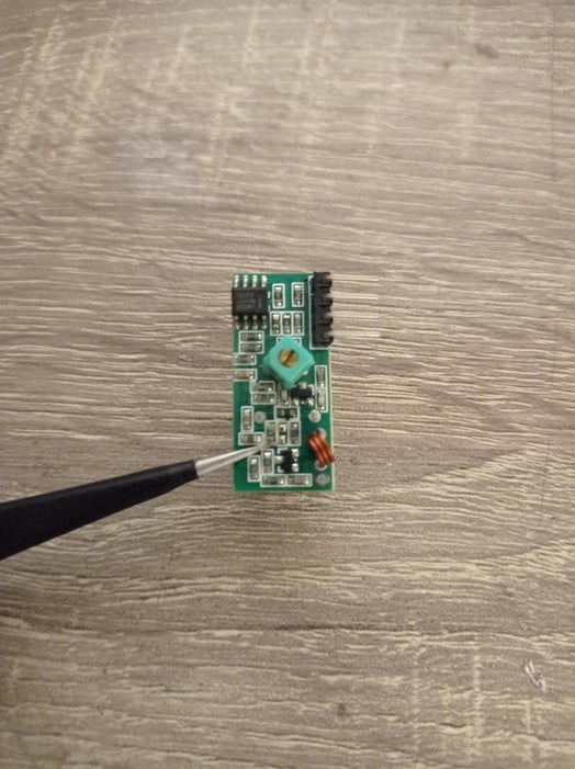 This module is a pair of small radio-frequency (RF) electronic modules which are used to send and receive radio signals between two devices. This is the reason why two Arduino boards are required for this project (one for a transmitter, and one for a receiver). The transmitter module is used to transmit data, and the receiver is used to receive data.
Step 4: Antennas
 This is a small radio-frequency module, which means that it requires two antennas for successful wireless communication, and the antenna is just a piece of wire.
Those two boards have 3 pins (receiver board have 4 pins but second and third pins are connected together- and that is a data pin)
positive voltage-VCC,
ground-negative supply,
data,
in this step solder 3 wires, one wire goes to the VCC pin, the other one goes to the ground (-), and the third one goes to the data pin.
And also note that a longer antenna is required for this to work at a greater distance.
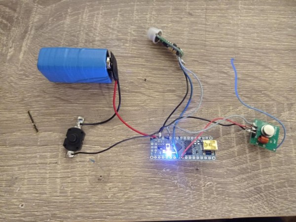
Step 5: Transmitter
 Wiring it up is pretty simple and it goes like this: connect VCC pins (from a transmitter and PIR sensor) together, then to Arduino 5v pin. Connect all GND-s together, then connect the output of a PIR sensor to pin D4 on the Arduino board, and then connect the data pin (from the transmitter) to pin D5 on the Arduino board.
Step 6: Receiver
 The receiver is also pretty simple to wire up and it goes like this: connect VCC pin to Arduino 5v pin, connect GND from receiver board to GND on Arduino board, connect LED negative side (cathode) to GND, then connect LED positive side (anode) to one end of a resistor (100 ohms) and the other end of a resistor goes to pin 13.
Step 7: Arduino Codes
There are two codes for this project one for a transmitter, and one for a receiver.
Step 8: Transmitter Box
 I decided to use this small wooden box because it has a home decor type of look to it, and that makes it a great box for installing a PIR sensor in it.
In order to install a PIR sensor in this box, I first measured the diameter of the PIR sensor (10 mm), then I used a 10 mm drill bit to make a hole for a PIR sensor.
Step 9: Transmitter Box (electronics)
 In this step install a small ON-OFF switch and a 9v battery connector.
Wiring it up is also simple and it goes like this: battery negative goes to the one side of a switch, then from a switch to the GND on the Arduino board, battery positive goes to the VIN pin on the Arduino board, and that is it.
Step 10: Receiver Box
 In this step make a hole for the switch and 5mm LED.
I first measured the dimensions of a switch, then I traced them on the box, and then I cut it out. And for the LED hole I used a 5mm drill bit.
Step 11: Receiver Box (electronics)

Read more: DIY Arduino Wireless Motion Alarm System