Ham radio is the use of radio frequency spectrum for purposes of non-commercial exchange of messages, wireless experimentation, self-training, etc. Developing a ham radio project may requires using an antenna analyser, a device that is used for measuring input frequency and impedance.
There are many types of antenna analyzers such as Anritsu VNA Master, RigExpert, Mini VNA, and others. But these analysers are very expensive to buy. They starts from $500 up to thousands of dollars and they are also hard to hack. This guide shows how to construct and use a DIY HF antenna analyzer using Arduino for less than $50.
The project consists of three parts; a Microcontroller, AD9850 DDS module, and a VSWR Bridge.
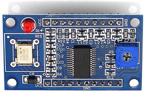
The AD9850 is a CMOS highly integrated device that uses advanced Direct Digital Synthesis (DDS) technology coupled with an internal high speed, high performance, D/A converter and comparator, to form a complete digitally programmable frequency synthesizer and clock generator function.

AD9850 module is a $9 stable, low drift VFO (Variable Frequency Oscillator) fed by a 125 MHz crystal clock. The module covers from 0 to 40 MHz, which are all the HAM HF(High Frequency) frequencies. There are 4 output pins on the device, 2 for Sine Waves (only one Frequency at a time) and two Square wave outputs. The blue pot on the board adjusts the duty cycle of the Square Wave Outputs but has no effect on the Sine Wave Outputs.
AD9850 features:
- Signal Frequency output range: 0-40MHz
- 4 Signal outputs; 2 sine wave outputs and 2 square wave outputs
- DAC SFDR > 50 dB @ 40 MHz AOUT
- 32-Bit Frequency Tuning Word
- Simplified Control Interface: Parallel Byte or Serial Loading Format
- Phase Modulation Capability
- +3.3 V or +5 V Single Supply Operation
- Low Power: 380 mW @ 125 MHz (+5 V)
- Low Power: 155 mW @ 110 MHz (+3.3 V)
- Power-Down Function

The VSWR (voltage standing wave ratio) bridge is an impedance bridge circuit, which is used to measure the ratio of maximum voltage (Vf+Vr ) to the minimum voltage (Vf-Vr) on a transmission line. The bridge will balanced (0 volts across the detector) only when the test impedance exactly matches the reference impedance. This bridge is easy and cheap to implement and works with up to few GHz frequencies.
Read More: Build Your Own Cheap Antenna Analyser