This mini project is involved to use Arduino to control submersible watre pump when soil reach below or above predefined moisture level.
How it works 
1. Soil moisture sensor is reading analog signal which transmit to Arduino.
2. Arduino control submersible water pump ON or OFF. Water pump operates when moisture level reach predefined value. Also, the water pump shall be stopped when reach predefined value.
3. Ultrasonic sensor is used to monitor predefined value of low water level. Warning sound is provided by buzzer when low water level detected. User is required to refill water to water tank manually.
4. The submersible water pump cannot be operated when low water level even if moisture level reach below or above predefined moisture value.
Step 1: Hardware/PCB List
 Hardware
-> Arduino UNO x 1 no.
-> 5V soil moisture sensor c/w digital and analog output x 1 no.
-> 5V Ultrasonic sensor (HC-SR04) x 1 no.
-> 5V USB type submersible water pump x 1 no.
-> 5V buzzer x 1 no.
-> bunch of rainbow wire with connector (male – male, male – female)
-> 9V battery x 1 no.
-> 1.2V NiMh AA rechargeable battery x 8 nos. (8 x 1.2V = 9.6V)
-> 5000mAh portable battery charger x 1 no.
-> 280mm (L) x 280mm (W) x 130mm (H) weatherproof type enclosure x 1 no.
PCB
-> 5V voltage regulator circuit x 1 no.
-> USB interfacing circuit x 1 no.
Step 2: Functions of Hardware/PCB
1-> Arduino UNO
It used to keep reading analog signal from soil moisture sensor. In addition, It controls submersible water pump ON/OFF when reach predefined moisture level. Also, it monitors low water level.
2-> 5V soil moisture sensor
This sensor can provide digital signal or analog signal to Arduino.
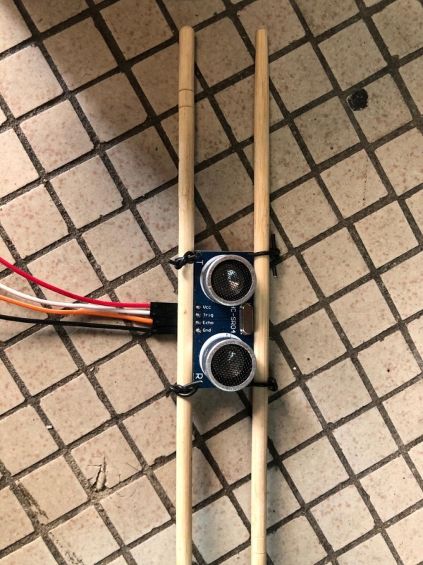
3-> 5V Ultrasonic sensor
This sensor keep monitoring water level. Signal shall be sent to Arduino when reach predefined value.
4-> 5V USB type submersible water pump
It is controlled by Arduino which can turn ON/OFF submersible water pump automatically.
5-> 5V buzzer x 1 no.
Sound to warn low water level occur.
6-> Bunch of rainbow wire with connector
Interfacing necessary component and circuits
7-> 9V battery
Independent power supply for 5V regulator.
8-> 1.2V NiMh AA rechargeable battery
Independent power supply for Arduino.
9-> 5000mAh portable battery charger
Independent power supply for 5V submersible water pump.
10-> Weatherproof type enclosure
For arrangement all necessary component and provide weatherproof feature.
11-> 5V voltage regulator circuit (PCB)
Power supply of soil moisture sensor is provided by this voltage regulator.
12-> USB interfacing circuit (PCB)
Provide interfacing to 5000mAh portable battery charger, 5V submersible water pump and signal from Arduino.
Step 3: Automatic Irrigation System Control Logic
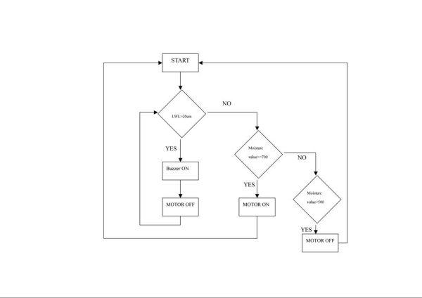 Firstly, Arduino read signal from ultrasonic sensor to check whether water level greater than 20cm or not. Buzzer will sound for warning low water level in water tank. The submersible water pump is not allow to operate due to programming.
Secondly, Arduino check whether moisture value greater or equal to 700 when low water level smaller than 20cm. If so, Arduino will transmit signal to USB interfacing circuit to turn the submersible water pump ON. Otherwise, it checks moisture valve whether smaller than 500. The USB interfacing circuit receive signal from Arduino to turn the water pump OFF.
According to supplier recommendation, the water pump become malfunction/burn out when it operates without water. Hence, water level monitor is implemented to prevent pump operate even if moisture value reach below or above predefined moisture value.
Step 4: Schematic Diagram of 5V Voltage Regulator Circuit
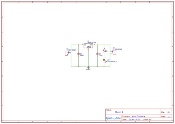 This 5V voltage regulator circuit is power from 9V battery and output 5V for soil moisture sensor. Necessary component show as below
-> 7805 x 1 no.
-> 2 ports power connector x 2 nos. (1 for INPUT & 1 for OUTPUT)
-> 330nF ceramic capacitor x 1 no.
-> 110nF ceramic capacitor x 1 no.
-> 5mm LED x 1 no. (visual inform user output is available)
-> 470 Ohm resistor x 1 no.
The schematic drawn by EasyEDA. In addition, this program can generate PCB base on schematic. It provides autoroute feature for you. However, you can route the track manually too.
Step 5: Schematic Diagram for USB Interfacing Circuit
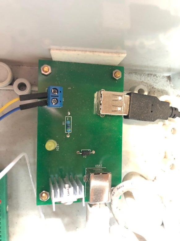 This USB interfacing circuit is used for provide connection for USB and 2 ports power connectors. Necessary component show as below
-> TIP120 transistor x 1 no.
-> 2 ports power connector x 1 no.
-> 10k resistor x 1 no.
-> 5mm LED x 1 no. (visual inform user signal is ON or OFF status)
-> 1N4007 diode x 1 no.
-> 90 degree USB type A x 1 no.
-> 90 degree USB type B x 1 no.
5000mAh portable battery charger connect to USB type B. 5V DC submersible water pump connect to USB Type A . 2 ports power connector connect to Arduino PIN to check signal from Arduino. Arduino generate HIGH signal if dry soil detected. On the contrary, LOW signal shall be generated if moisture reach predefined valve. Transistor shall act as ON/OFF switch of this circuit. HIGH signal turn the water pump ON but the water pump will be stopped when LOW signal from Arduino.
As i mentioned above schematic, this schematic is drawn by EasyEDA too.
Step 6: Wiring Diagram
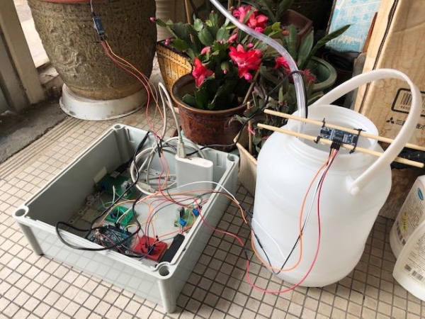
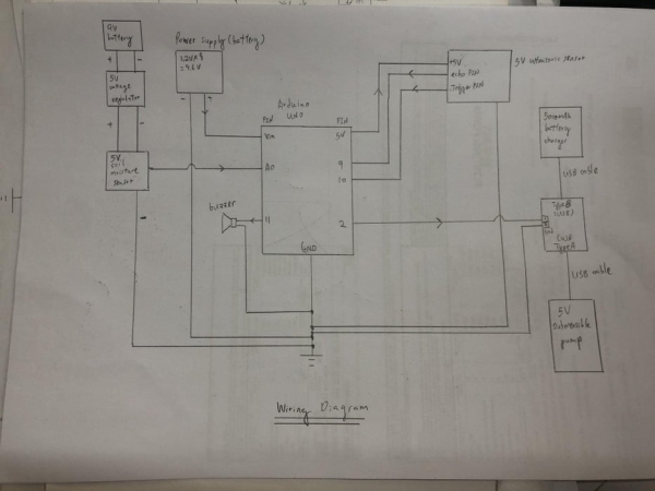 This wiring diagram shows connection for this automatic irrigation system. Power supplies are provided independently because Arduino 5V output supply provide insufficient power to operate ultrasonic sensor and soil moisture sensor at the same time. On the other hand, the water pump is connected to separate power supply too. Referring to nameplate of water pump, 1.5W power consumption is required for this water pump.
P=I x V
1.5W = I x 5V
I = 0.3A or 300mA
According to Arduino specification, maximum dc current per I/O pin is 40mA. Hence, it is good to use external power supply rather than Arduino 5V output for supplying voltage to equipment such as fan, water pump and so on.
Step 7: Programming and Upload to Arduino
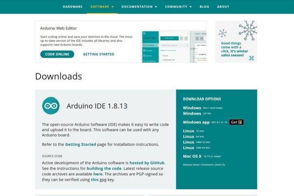 Arduino IDE 1.8.13 is used for programming. You can download this IDE from Arduino webpage. C language is adopted to program Arduino board. Program can be complied once program is ready. Please be informed that program cannot be uploaded if any errors found during comply. Once errors are clear, you can upload program to Arduino.?
