This sketch is used by Exercise: Sensor Fade.
Full Source Code
The full code is all in one file SensorFade.ino.
// SensorFade - read a photosensor and control several LEDs at different brightnesses
//
// Copyright (c) 2016, Garth Zeglin. All rights reserved. Licensed under the
// terms of the BSD 3-clause license as included in LICENSE.
//
// This program assumes that:
//
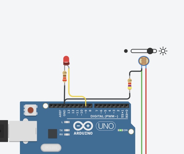
// 1. A sensor is attached to analog input A0. The exercise uses a photocell
// with a 5.6K pull-down resistor in a voltage divider.
//
// 2. Pins 5 and 6 are attached via dropping resistors to LEDs which connect to
// ground. The output pin is used to source current; the logic will be
// positive (HIGH = ON).
// ================================================================================
// Definitions of constant values.
const int LED1PIN = 5;
const int LED2PIN = 6;
const int SENSORPIN = A0;
const int BLINKDELAY = 500; // interval between fixed blinks, in milliseconds
// The following declarations define scaling constants and thresholds for
// interpreting the analog input signal. The input range for a typical
// photocell with a 5.6K bias resistor is centered around 4 volts. This can be
// verified using a voltmeter to check the range of inputs on A0 and adjust the
// following V_DARK and V_LIGHT values. Note the use of the scaling factors to
// scale the measured voltages into ADC units.
// These are physically measured voltages defining the typical dark and light
// input voltages. You may need to change these:
const float V_DARK = 3.5; // in Volts
const float V_LIGHT = 4.2; // in Volts
// These are properties of the Arduino analog-to-digital converter:
const float ADC_MAX_VOLTAGE = 5.0; // in Volts
const int ADC_RANGE = 1024; // in dimensionless ADC units
// These thresholds are calculated from the other constants.
const int V_LOW = V_DARK * (ADC_RANGE/ADC_MAX_VOLTAGE); // in dimensionless ADC units
const int V_HIGH = V_LIGHT * (ADC_RANGE/ADC_MAX_VOLTAGE); // in dimensionless ADC units
// ================================================================================
// Global variable declarations.
// Counter variable to keep to track of the number of update periods for
// defining the blinks of the onboard LED.
int led_cycle_count = 0;
// ================================================================================
// Configure the hardware once after booting up. This runs once after pressing
// reset or powering up the board.
void setup(void)
{
// Initialize the hardware digital pin 13 as an output. The 'OUTPUT' symbol
// is pre-defined by the Arduino system.
pinMode(LED_BUILTIN, OUTPUT);
// Initialize the external LEDs as outputs.
pinMode(LED1PIN, OUTPUT);
pinMode(LED2PIN, OUTPUT);
// Produce a timed sequence of blinks to indicate the start of the program.
fixed_blink_pattern(); // this function is defined below
}
// ================================================================================
// Run one iteration of the main event loop. The Arduino system will call this
// function over and over forever.
// This function continuously maps changes of the photocell input level into
// pulse-width-modulated (PWM) output on the LED.
void loop(void)
{
// Read the voltage on the sensor input. This function returns a value
// between 0 and 1023 representing a voltage between 0 and 5V.
int sensor = analogRead(SENSORPIN);
// Compute proportional signals to drive the LEDs by mapping an input range to
// the output range. The input thresholds are defined above in this file. The
// PWM output is scaled from 0 to 255.
int led1_value = map(sensor, V_LOW, V_HIGH, 0, 255);
int led2_value = map(sensor, V_LOW, V_HIGH, 255, 0); // symmetric scaling
// Emit PWM signals with a proportional average power; the LEDs will have
// variable brightness. The constrain function will ensure the values stay
// within the correct limits.
analogWrite(LED1PIN, constrain(led1_value, 0, 255));
analogWrite(LED2PIN, constrain(led2_value, 0, 255));
// Blink the onboard LED. led_cycle_count is a global variable defined above.
if (led_cycle_count == 0) {
digitalWrite(LED_BUILTIN, LOW);
} else if (led_cycle_count == 32) {
digitalWrite(LED_BUILTIN, HIGH);
}
// Increase the cycle count for the next iteration.
if (led_cycle_count < 63) {
led_cycle_count += 1;
} else {
led_cycle_count = 0;
}
// Delay for a short interval to create a periodic sampling rate.
delay(20);
}
Read more: Arduino Sketch SensorFade